Submerged arc welding method for steel plate

a technology of submerged arc welding and steel plate, which is applied in the direction of welding/soldering/cutting articles, other domestic articles, manufacturing tools, etc., can solve the problems of easy surface defects, increased the possibility of lack of penetration, and decreased welding heat input, so as to reduce welding heat input, wide bead width, and reduce welding heat input

Inactive Publication Date: 2014-11-27
JFE STEEL CORP
View PDF1 Cites 3 Cited by
  • Summary
  • Abstract
  • Description
  • Claims
  • Application Information

AI Technical Summary

Benefits of technology

[0023]According to the present invention, it is possible to decrease welding heat input and secure a depth of penetration. Further, a weld reinforcement height can be lowered, and a wide bead width can be achieved. Therefore, the present invention is advantageous for submerged arc welding and exhibits a significant industrial effect.

Problems solved by technology

On the other hand, seam welding of large-diameter steel pipes has the problem of deterioration in toughness of welded zones, particularly welded heat affected zones, and thus has the need to decrease welding heat input as much as possible in order to improve toughness of welded zones.
However, a decrease in welding heat input increases the possibility of producing lack of penetration, easily produces an unmelted part, and causes the problem of easily producing surface defects such as undercut and the like.
However, the technique disclosed in Patent Literature 3 includes inputting arc energy in the thickness direction of a plate to suppress melting in the width direction of steel plate, thereby causing a narrow bead width and the problem of easily producing surface defects such as undercut and the like.
However, the technique disclosed in Patent Literature 4 exhibits the effect of widening a bead width but requires a large current to be supplied for significantly extending a bead width, resulting in an increase in welding heat input and the problem of deterioration in toughness of a welded zone, particularly a welded heat affected zone.
Also, the supply of a large current increases an amount of a wire melted and increases a reinforcement height, and thus a groove shape is required to be newly designed.

Method used


Image

  • Submerged arc welding method for steel plate
  • Submerged arc welding method for steel plate
  • Submerged arc welding method for steel plate

Examples


examples

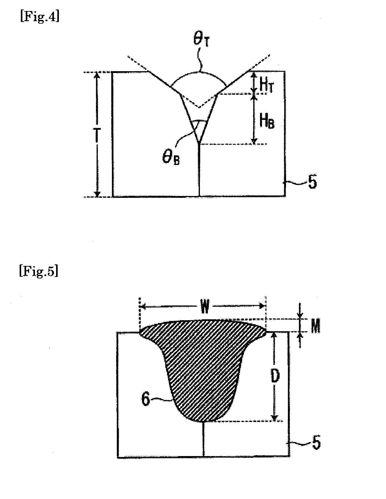
[0055]After a two-step groove was formed in the steel plate 5 having a thickness T of 31.8 mm as shown in FIG. 4, a weld joint shown in FIG. 5 was formed in one pass of submerged arc welding using 3 to 5 electrodes. Table 1 shows groove shapes, Table 2 shows welding conditions, Table 3 shows arrangements of electrodes, and Table 4 shows setting of welding currents.

TABLE 1Bottom layerSurface layerGrooveGrooveGrooveGrooveGroovecross-Thick-angledepthangledepthGroovesectionalNum-nessθBHBθTHTwidthareaber(mm)(°)(mm)(°)(mm)(mm)(mm)131.8508.01005.019.496.9231.8406.51006.520.296.5331.87010.01003.021.2122.8431.8508.01005.019.496.9531.8508.01005.019.496.9631.87013.0——18.2118.3731.8366.51006.519.791.5831.8808.01005.025.3150.6931.87010.01303.026.9131.31031.8505.01008.023.7125.21131.8508.01005.019.496.91231.8508.01005.019.496.91331.8508.01005.019.496.91431.8508.01005.019.496.9

TABLE 2#1*#2*#3*#4*#5*WeldingCur-Volt-WireCur-Volt-WireCur-Volt-WireCur-Volt-WireCur-Volt-WireWeldingheatrentagediameterre...


PUM

PropertyMeasurementUnit
diameteraaaaaaaaaa
groove angle θBaaaaaaaaaa
groove angle θTaaaaaaaaaa

Abstract

Disclosed is a submerged arc welding method capable of an attempt to enhance toughness of a welded zone with low heat input and an attempt to decrease a weld reinforcement height by suppressing excessive melting of a wire, and capable of achieving a deep depth of penetration and a wide bead width. In the submerged arc welding method, a first electrode at the head in a welding direction has a wire diameter of 2.0 to 3.2 mm and a current density of 145 A/mm2 or more, second and subsequent electrodes are arranged behind the first electrode in a line, and a groove formed in a steel plate has a two-step groove shape satisfying θBT where θB is a groove angle of a bottom layer, and θT is a groove angle of a surface layer.

Description

TECHNICAL FIELD[0001]The present invention relates to submerged arc welding of steel plates and to submerged arc welding suitable for seam-welding large-diameter steel pipes such as UOE steel pipes, spiral steel pipes, and the like.BACKGROUND ART[0002]Submerged arc welding (for example, refer to Patent Literatures 1 and 2) using two or more electrodes is popularized as seam welding of large-diameter-steel pipes such as UOE steel pipes, spiral steel pipes, and the like, and double one layer welding with high efficiency in which the inner side is welded in one pass and the external side is welded in one pass is widely used in view of improvement of productivity of large-diameter-steel pipes.[0003]In double one layer welding, it has the need to secure a depth of penetration for sufficiently overlapping an internal weld metal with an external weld metal so as not to produce an unmelted part, and thus welding is generally performed by supplying a large current of 1000 A or more.[0004]On ...

Claims


Application Information

Patent Timeline
Patent Type & Authority Applications(United States)
IPC IPC(8): B23K9/18
CPCB23K9/188B23K33/006B23K2101/06B23K2103/04
Inventor ISHIGAMI, ATSUSHIHAYAKAWA, NAOYAYANO, KOJI
Owner JFE STEEL CORP
Why Eureka
Try Eureka