
Light source device and filament

a light source device and filament technology, applied in the field of filament, can solve the problems of inability to markedly improve the conversion efficiency of such a technique, and inability to provide efficient reabsorption, etc., to achieve high visible luminous efficiency, reduce infrared light radiation, and enhance visible light radiation

Active Publication Date: 2014-11-27
STANLEY ELECTRIC CO LTD
View PDF9 Cites 2 Cited by
  • Summary
  • Abstract
  • Description
  • Claims
  • Application Information

AI Technical Summary

Benefits of technology

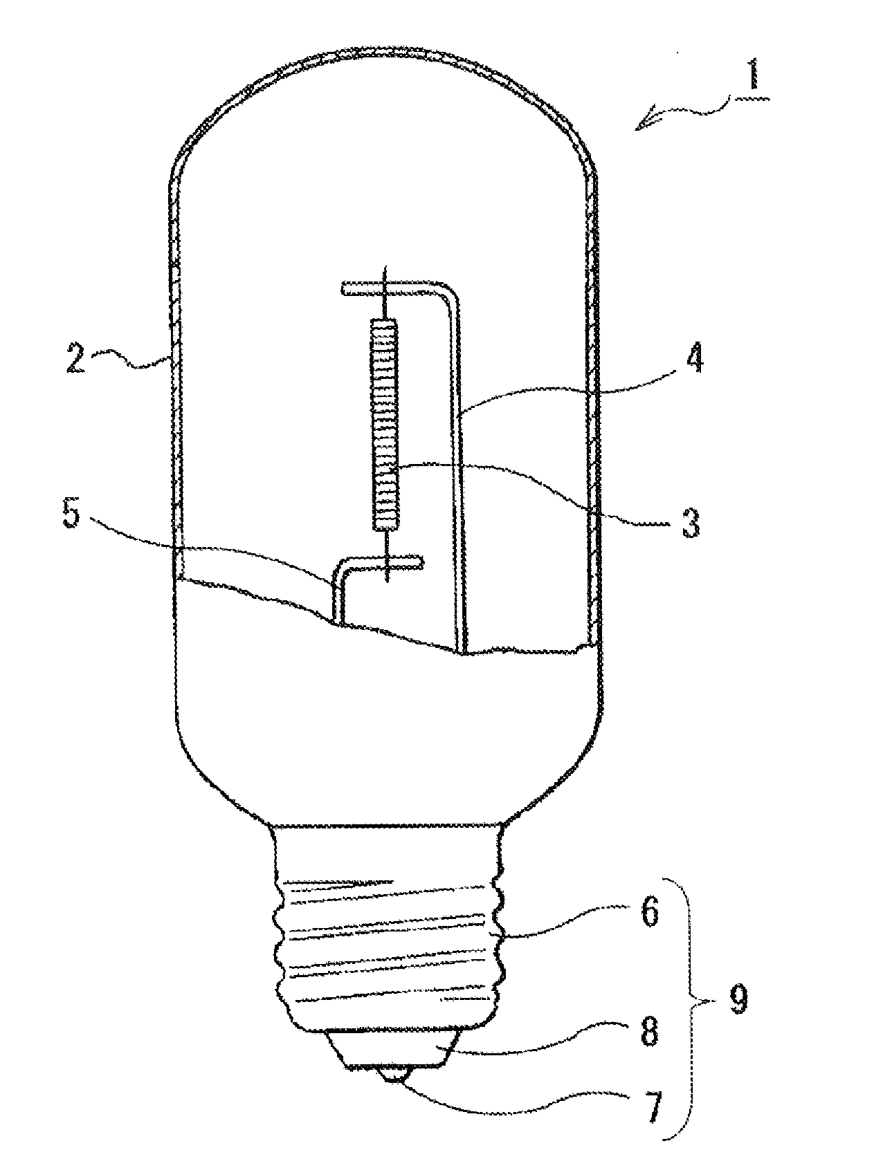
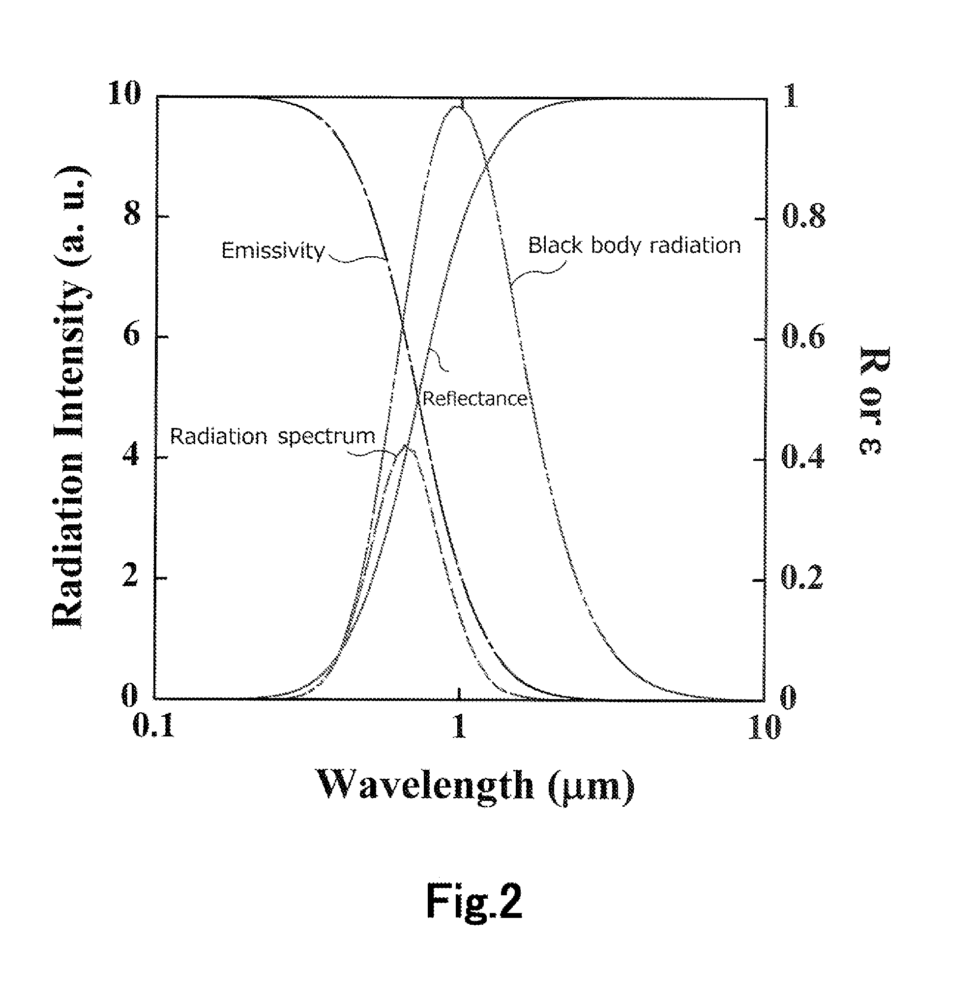
The present invention relates to a light source device that can reduce infrared light radiation and enhance visible light radiation. This is achieved by creating a filament with high reflectance for infrared light and low reflectance for visible light. This results in a light source device that has high visible luminous efficiency.

Problems solved by technology

Although the effect for prolonging the lifetime is realizable with the technique of using the halogen cycle such as those disclosed in Patent documents 1 and 2, it is difficult to markedly improve the conversion efficiency with such a technique, and the efficiency currently obtainable thereby is about 20 lm / W.
Further, the technique of reflecting infrared lights with an infrared light reflection coating to cause the reabsorption by the filament such as those described in Patent documents 3 to 5 cannot provide efficient reabsorption of infrared lights by the filament, since the filament has a high reflectance for infrared lights as high as 70%.
Furthermore, the infrared lights reflected by the infrared light reflection coating are absorbed by the parts other than the filament, for example, the part for holding the filament, base, and so forth, and are not fully used for heating the filament.
For these reasons, it is difficult to significantly improve the conversion efficiency with this technique.
Concerning the technique of suppressing infrared radiation lights with a microstructure such as those described in Patent documents 6 to 9, there have been reported the effects of enhancing and suppressing lights of only an extremely small part of the wavelength region of the infrared radiation spectrum as reported in Non-patent document 1, but it is extremely difficult to suppress infrared radiation lights over the wide total range of the infrared radiation spectrum.
Therefore, it is considered that it is difficult to attain marked improvement in the efficiency with this technique.
Furthermore, the production of the microstructure requires use of a highly advanced microprocessing technique such as the electron beam lithography, and therefore light sources produced by utilizing it becomes extremely expensive.
In addition, it has also a problem that even though a microstructure is formed on a W substrate, which is a high temperature resistant material, the microstructure on the surface of W is melted and destroyed at a heating temperature of about 1000° C.

Method used


Image

  • Light source device and filament
  • Light source device and filament
  • Light source device and filament

Examples


specific examples

[0075]As the filaments of Examples 1 to 9 as specific examples, there are prepared filaments in which the substrate is constituted with Ta, and 9 kinds of combinations described later of the materials of the first layer 21 and the second layer 22 of the infrared light-reflecting film 20 are used.

[0076]In all the examples, as the visible light-absorbing film 30, an SiC film to which Ta metal microparticles (particle diameter, 3 nm) are added at a concentration of 0.1% is used. The thickness of the visible light-absorbing film 30 is about 200 nm. Further, as the visible light antireflection coating film 40, an MgO film is used, and the thickness thereof is 80 nm.

[0077]The substrate 10 is produced by a known process such as sintering and drawing of a material metal. The substrate is formed in a desired shape, for example, in the form of wire, rod, thin plate, or the like.

[0078]The surface of the substrate is polished with two or more kinds of diamond abrasive grains, and thereby proces...


PUM


Abstract

A light source device comprising a filament showing high electric power-to-visible light conversion efficiency is provided. The light source device of the present invention comprises a translucent gastight container, a filament disposed in the translucent gastight container, and a lead wire for supplying an electric current to the filament. The filament comprises a substrate formed from a metal material and a visible light-absorbing film covering the substrate. The visible light-absorbing film is transparent to lights of infrared region. The reflectance of the substrate for visible lights is thereby made low, and the reflectance of the substrate for infrared lights is thereby made high. Therefore, radiation of infrared lights is suppressed, and visible luminous efficiency can be enhanced.

Description

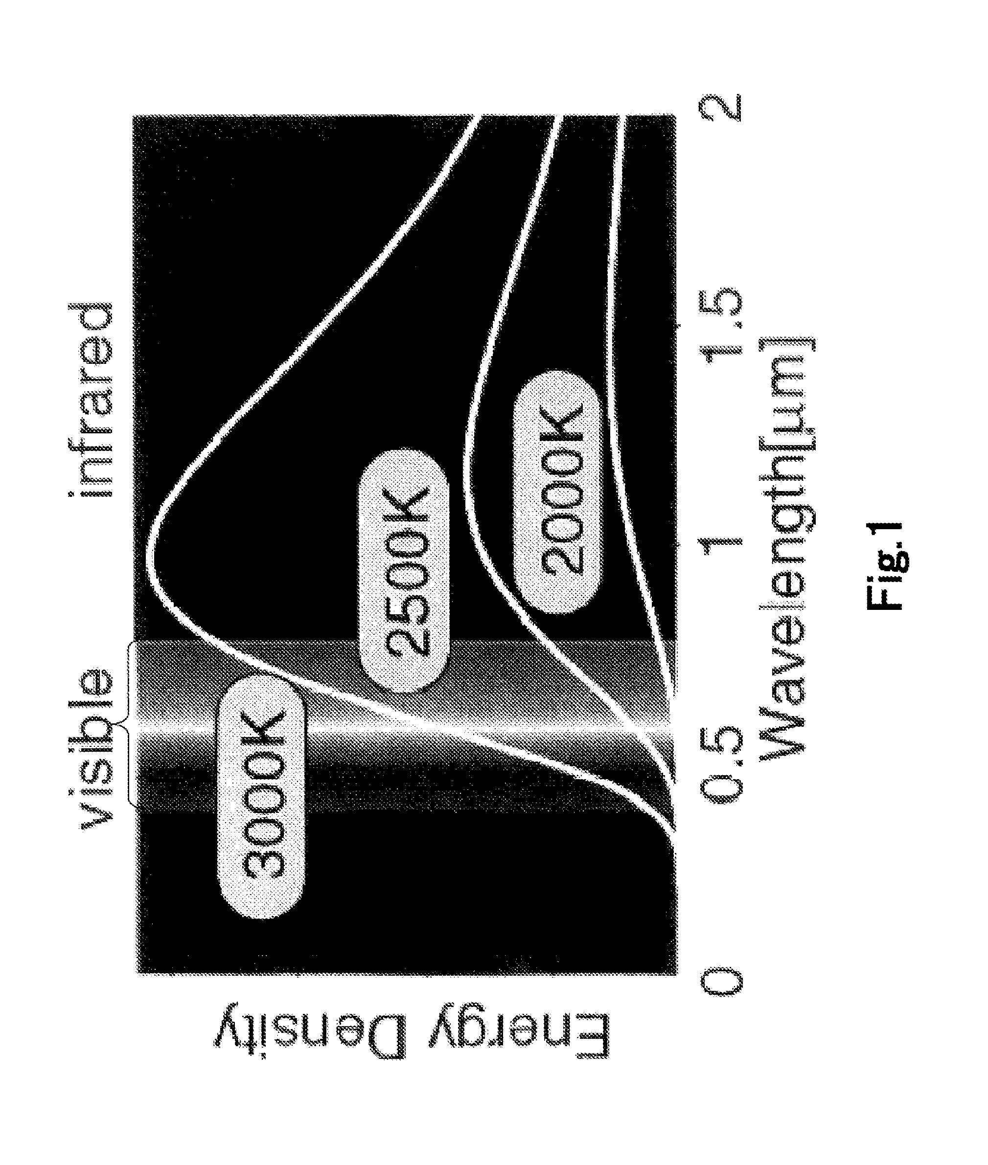
TECHNICAL FIELD[0001]The present invention relates to a filament for light sources showing improved energy utilization efficiency, and it also relates to, in particular, a light source device, especially an incandescent light bulb and a near infrared or thermoelectronic emission source, utilizing such a filament.BACKGROUND ART[0002]There are widely used incandescent light bulbs which produce light with a filament such as tungsten filament heated by flowing an electric current through it. Incandescent light bulbs show a radiation spectrum close to that of sunlight providing superior color rendering properties, and show high electric power-to-light conversion efficiency of 80% or higher. However, 90% or more of the components of the light radiated by incandescent light bulbs consists of infrared radiation components as shown in FIG. 1 (in the case of 3000K in FIG. 1). Therefore, the electric power-to-visible light conversion efficiency of incandescent light bulbs is as low as about 15...

Claims


Application Information

Patent Timeline
Patent Type & Authority Applications(United States)
IPC IPC(8): H01K1/26H01K1/04
CPCH01K1/04H01K1/26H01K1/10H01K3/02
Inventor KAWAKAMI, YASUYUKIMATSUMOTO, TAKAHIROSAITO, TAKAOEMOTO, KEI
Owner STANLEY ELECTRIC CO LTD
Learn More