
Periodically resetting integration angle demodulation device and method using the same

a demodulation device and angle technology, applied in the field of angle demodulation device and method using the same, can solve the problems of limited carrier frequency limit, inflexible design of pmdi optical sensing system, affecting sensor bandwidth, etc., and achieves the effect of reducing the number of circuit elements, high speed, and small volum

Inactive Publication Date: 2014-11-27
NAT CHIAO TUNG UNIV
View PDF6 Cites 11 Cited by
  • Summary
  • Abstract
  • Description
  • Claims
  • Application Information

AI Technical Summary

Benefits of technology

The present invention is an angle demodulation device and method using a periodically resetting integration technology. It aims to achieve small size, high sensitivity, high reliability, and high performance with high condition-adapting properties. Additionally, it provides a simple architecture that reduces the design difficulty of the optical sensing system and resolves issues of linearity and signal distortion. It also reduces capacitances used for integrated circuit realization and improves the yield of the optical sensing system.

Problems solved by technology

As a result, φc is limited to 2.2, which is not flexible enough to design the optical sensing system of PMDI.
In addition, the upper limit of a carrier frequency is limited, thereby affecting a bandwidth of the sensor.
Theoretically, the upper limit of the bandwidth of the sensor is 1 / 10 f. Thus, it is difficult for the circuit architecture to design an integrated circuit (IC) since each element of the circuit has complex design and the whole circuit area required is too large to be encapsulated in a chip.
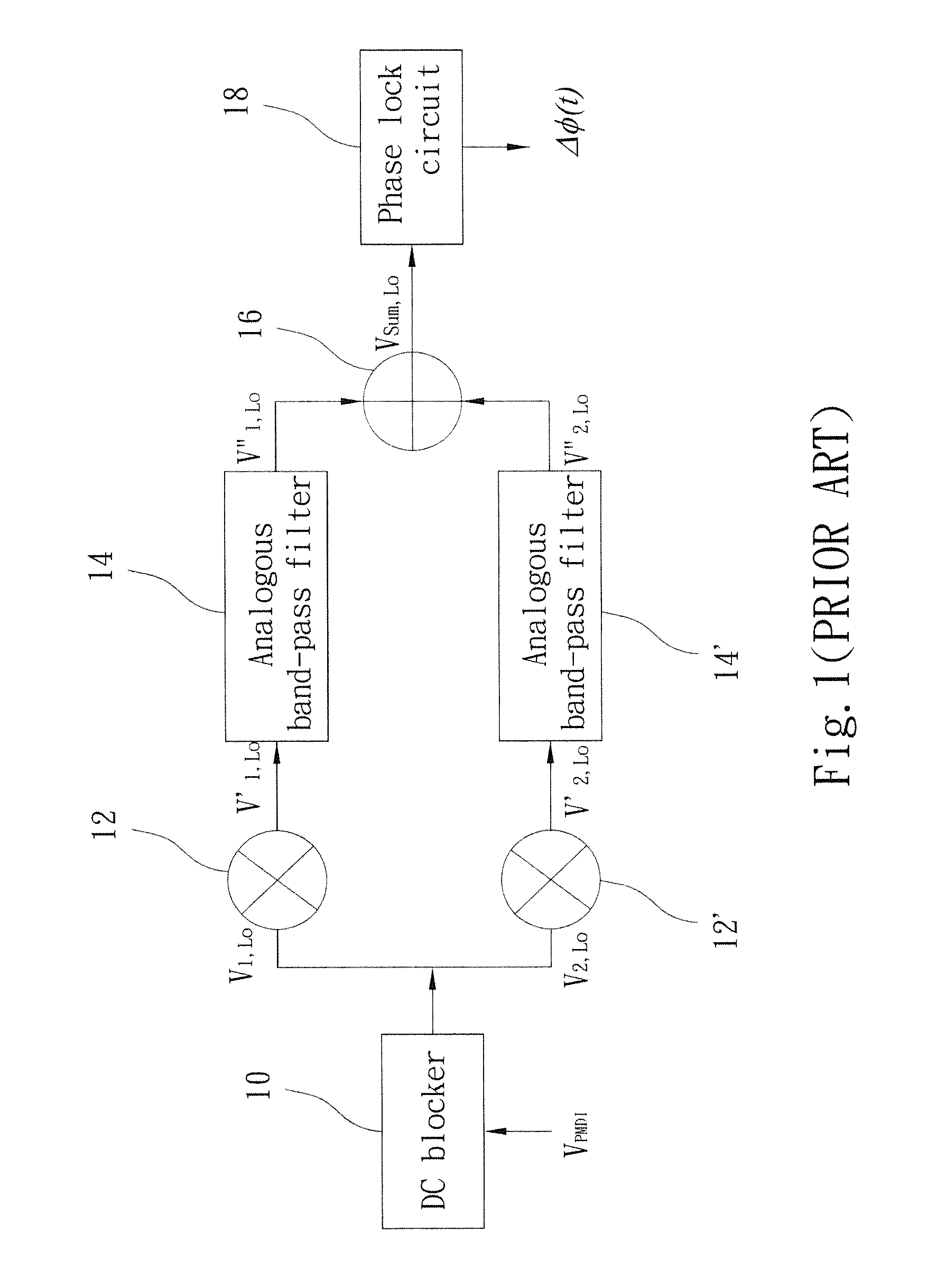
Specifically, two band-pass filters 14 and 14′ required have complex design and large volumes since the design requires the information of a single frequency (fc, 2fc).
The demand limits a possibility to use the architecture to realize an IC.
If the analogous multipliers have nonlinearity, harmonic waves appear in the result of the analogous multipliers to result in distortion.
The instrument and the oscillator consume the cost and cannot provide pure sine waves with frequency of fc and 2fc, which results in distortion of the demodulated signal.
And, the problems of too large areas of resistors and capacitors, high design complexity, high power consumption and bad linearity exist.

Method used


Image

  • Periodically resetting integration angle demodulation device and method using the same
  • Periodically resetting integration angle demodulation device and method using the same
  • Periodically resetting integration angle demodulation device and method using the same

Examples


Embodiment Construction

[0029]The purpose of microminiaturizing a whole system is not achieved due to the fact that a synthetic heterodyne demodulation circuit is too large fabricated on a large circuit board. In order to overcome the problem, the present invention provides a periodically resetting integration angle demodulation device to simplify the circuit.

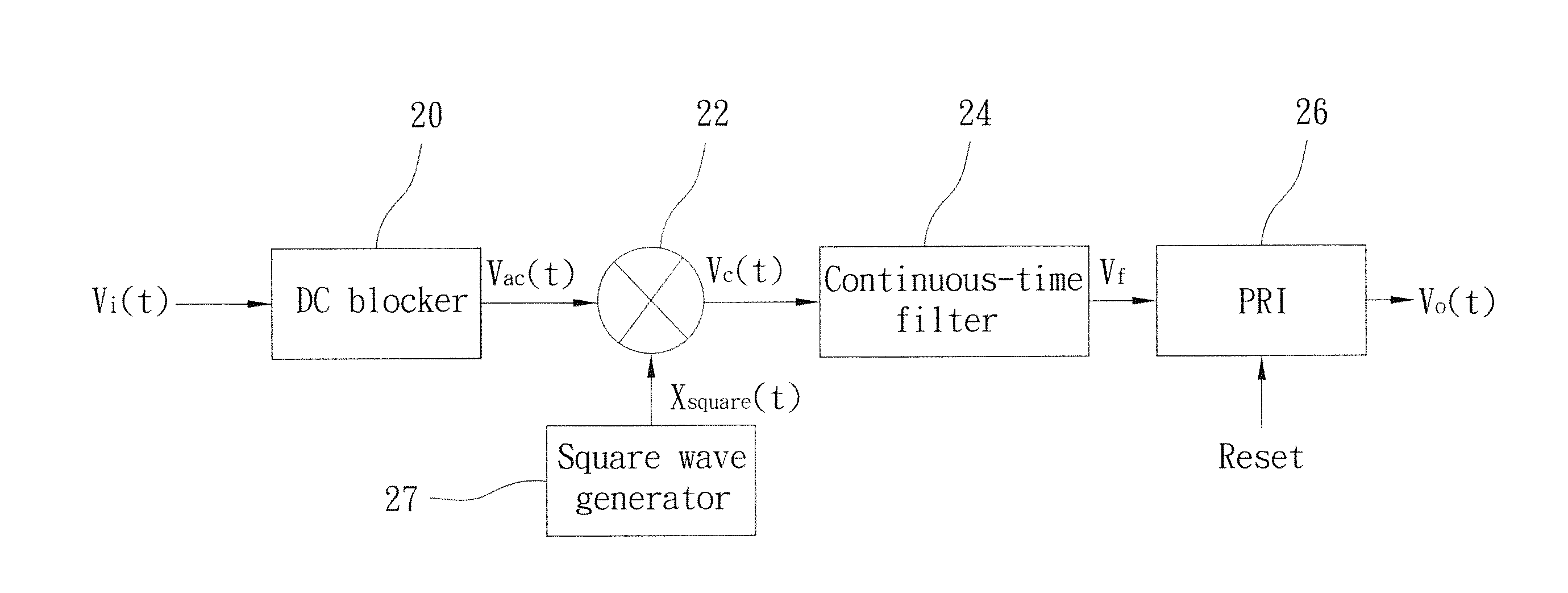
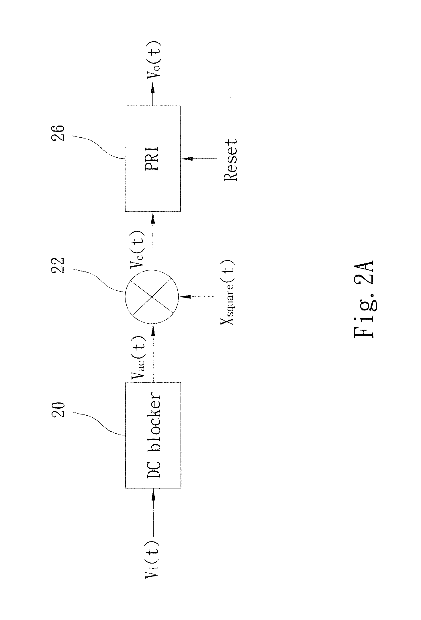
[0030]Refer to FIG. 2A, which is a circuit of the present invention. The angle demodulation device comprises a direct-current (DC) blocker 20, a waveform multiplier 22 and a periodically resetting integration (PRI) 26. The DC blocker 20 is coupled to an optical sensing system (not shown) and uses the optical sensing system (PMDI) to send out an angle modulation signal (VPMDI(t)) to the DC blocker 20. The DC blocker 20 is coupled to the waveform multiplier 22. The DC blocker 20 receives the angle modulation signal to filter out a DC signal of the angle modulation signal, and sends out an alternative-current (AC) signal (Vac(t)) to the waveform multipli...


PUM


Abstract

A periodically resetting integration angle demodulation device and a method using the same is disclosed, which uses a waveform multiplier and a periodically resetting integrator to modulate a continuous-time angle modulation signal into a discrete-time signal. The waveform multiplier multiplies the continuous-time angle modulation signal by a square wave signal whose frequency is integer times a carrier frequency, and then transmits the continuous-time angle modulation signal to a periodically resetting integrated circuit. The periodically resetting integrated circuit performs integration during a carrier period to generate a discrete-time angle modulation output signal. The present invention can greatly reduce the difficulty for designing an optical sensing system in the front end without limiting a modulation depth. Besides, the present invention achieves a small volume, high speed, high sensitivity, high reliability, high performance and high condition-adapting properties.

Description

[0001]This application claims priority for Taiwan patent application no. 102117824 filed at May 21, 2013, the content of which is incorporated by reference in its entirety.BACKGROUND OF THE INVENTION[0002]1. Field of the Invention[0003]The present invention relates to an angle demodulation device and method using the same, particularly to a periodically resetting integration angle demodulation device and a method using the same.[0004]2. Description of the Related Art[0005]An optical sensing system is a sensor to measure acceleration, including those of a piezoresistive pressure sensor, a capacitive sensor, a piezoelectric sensor and an optical sensor, especially the optical sensor with better sensitivity. The optical sensor can apply to the system of high standard without disturbance of electromagnetic radiation, such as an advanced intelligent fuse system.[0006]Among all kinds of optical accelerometers, Path Matched Differential Interferometry (PMDI) is an effective accelerometer. ...

Claims


Application Information

Patent Timeline
IPC IPC(8): H03D3/00
CPCH03D3/00H03D3/04H03D2200/0021H03D2200/0049H03D7/161G01J9/02G01J9/04
Inventor HONG, HAO-CHIAOCHEN, YUN-TSEHUNG, SHAO-FENG
Owner NAT CHIAO TUNG UNIV
Learn More