
Method for transmitting and receiving fram in wireless local area network system and device supporting same

a wireless local area network and frame technology, applied in the field of wireless communications, can solve the problems of deteriorating data transmission and reception efficiency, and achieve the effect of reducing the length of a bit sequence included in the mac header, reducing the overall data throughput of the wlan system, and reducing the time consumed

Inactive Publication Date: 2014-11-27
LG ELECTRONICS INC
View PDF2 Cites 14 Cited by
  • Summary
  • Abstract
  • Description
  • Claims
  • Application Information

AI Technical Summary

Benefits of technology

This patent text is about a way to make data sent over a network faster and more efficiently by compressing the information in the header of the data. This reduces the amount of data that needs to be transmitted, which saves time and increases the overall data throughput of the network.

Problems solved by technology

Due to the nature of the physical layer in a next-generation WLAN system, the efficiency of data transmission and reception may be deteriorated.

Method used


Image

  • Method for transmitting and receiving fram in wireless local area network system and device supporting same
  • Method for transmitting and receiving fram in wireless local area network system and device supporting same
  • Method for transmitting and receiving fram in wireless local area network system and device supporting same

Examples


use example 1

[0144] Sensors and meters[0145]1a: smart grid-meter to pole[0146]1c: environmental / agricultural monitoring[0147]1d: industrial process sensors[0148]1e: healthcare[0149]1f: healthcare[0150]1g: home / building automation[0151]1h: home sensors

use example 2

[0152] Backhaul sensors and meta data[0153]Backhaul aggregation of sensors[0154]Backhaul aggregation of industrial sensors[0155]Use example 3. Extended range Wi-Fi[0156]Outdoor extended range hotspot[0157]Outdoor Wi-Fi for cellular traffic offloading

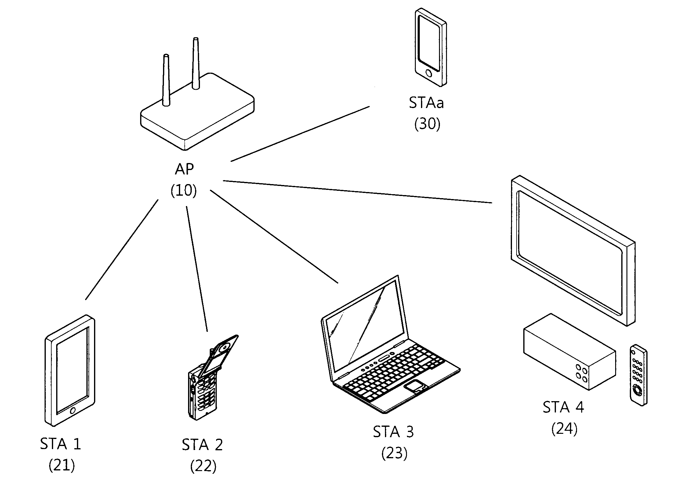
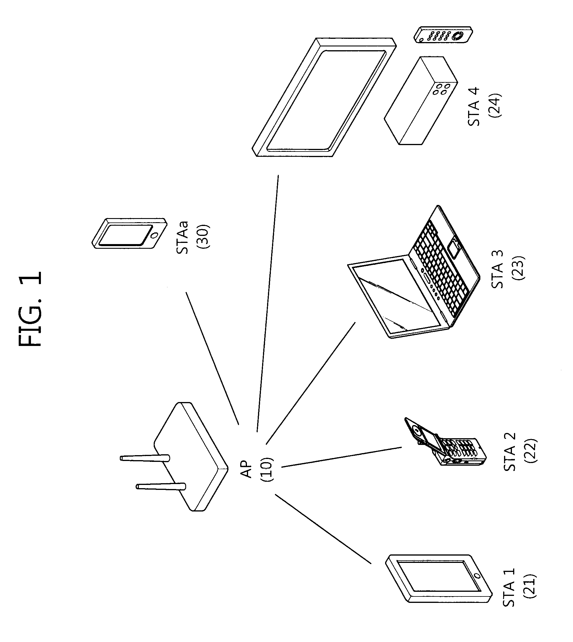
[0158]Use example 1 above, sensors and meters, is an example in which the above-described M2M is used. In usage 1, various types of sensor devices may be connected to an AP in a WLAN system to perform communication. Particularly in the case of smart grid, up to 6000 sensor devices may gain access to a single AP.

[0159]In use example 2, backhaul sensors and data meters, an AP providing broad coverage serves as a backhaul link of another communication system.

use example 3

[0160 aims to provide an outdoor extended range of hotspot communications such as extended home service coverage, campus service coverage, or shopping mall service coverage or aims to allow the AP to distribute over-loaded cellular traffic by offloading traffic for cellular mobile communication.

[0161]The present invention offers the format of a data unit for an apparatus that operates in a sub 1 GHz, as discussed in the next-generation WLAN standards. More specifically, the present invention suggests the architecture of an effective physical layer preamble for an apparatus operating in a sub 1 GHz. Hereinafter, data units as provided herein, i.e., PPDUs, may be sequentially sent in the form of OFDM symbols according to the order in which they are included in the field.

[0162]The communication in a sub 1 GHz has significantly broad service coverage as compared with the existing indoor-centered WLAN systems in view of the characteristics of the radio waves. For this, it may be implemen...


PUM


Abstract

Provided is a method for receiving a frame that is carried out by a station (STA) in a wireless local area network (WLAN) system. The method comprises receiving the frame from an access point (AP). The frame comprises a medium access control (MAC) header. The MAC header comprises a transmitter address (TA) field and a receiver address (RA) field. The RA field comprises identification information that is set on the basis of an association identifier (AID), which is allocated when the STA is associated with the AP.

Description

BACKGROUND OF THE INVENTION[0001]1. Field of the Invention[0002]The present invention concerns wireless communications, and more specifically, to methods of transmitting and receiving frames in a Wireless Local Area Network system and apparatuses supporting the same.[0003]2. Related Art[0004]With the growth of information communication technology, various wireless communication technologies have been recently developed. Among others, Wireless Local Area Network (WLAN) is a technology that allows for wireless access to the Internet at home or business or in a specific service area using a handheld terminal such as a personal digital assistant (PDA), a laptop computer, a portable multimedia player (PMP), etc.[0005]In contrast to the existing WLAN systems supporting High Throughput (HT) and Very High Throughput (VHT) using bandwidths of 20 / 40 / 80 / 160 / 80+80 MHz in a 2 GH and / or 5 GHz band, a WLAN system is offered that may be operated in a sub 1 GHz. When operated in a sub 1 GHz, a WLAN ...

Claims


Application Information

Patent Timeline
Patent Type & Authority Applications(United States)
IPC IPC(8): H04B7/26
CPCH04B7/2612H04W4/06H04W56/00H04W56/001H04W88/02H04W88/08
Inventor YOU, HYANG SUNSEOK, YONG HOPARK, JONG HYUN
Owner LG ELECTRONICS INC
Learn More