Austenitic alloy

Active Publication Date: 2014-11-27
SANDVIK INTELLECTUAL PROPERTY AB
View PDF5 Cites 5 Cited by
  • Summary
  • Abstract
  • Description
  • Claims
  • Application Information

AI Technical Summary

Benefits of technology

[0034]Nickel is an essential element for the purpose of ensuring a stable austenitic structure in the inventive alloy so that the formation of inter-metallic phases like sigma phase is suppressed. Sigma-phase is a hard and brittle intermetallic phase with chromium and molybdenum and is formed at elevated temperatures. Sigma phase has a negative impact of the ductility and elongation of the steel. By stabilizing the austenitic phase in the alloy, the formation of sigma phase is minimized. Nickel is therefore important for ensuring sufficient ductility and elongation of the steel. Nickel has also a positive effect on the corrosion resistance of the inventive alloy since it promotes the formation of a passive Cr-oxide film that suppresses further oxide growth, s c. scaling. The content of nickel should be at least 30 wt % in the inventive alloy in order to ensure structure stability, corrosion resistance and ductility. However, nickel is a relatively expensive alloy element and in order to maintain low production costs the content of nickel should be limited. Nickel further decreases the solubility of nitrogen in the alloy and therefore the content of nickel should not exceed 35 wt %.
[0036]Molybdenum is included in the inventive alloy in order to improve the hot corrosion resistance on the fire side of boiler tubes. Addition of Mo further improves the general-corrosion resistance of the inventive alloy. However, Mo is an expensive element and promotes precipitation of sigma-phase and thus invites deterioration of toughness of the steel. In order to ensure good hot corrosion resistance in the steel the content of molybdenum should be at least 3 wt %. The upper limit of molybdenum is 4 wt % to avoid precipitation of sigma phase.
[0038]Addition of copper can improve both the creep strength by precipitation of copper rich phase, finely and uniformly precipitated in the matrix. However, an excessive amount of copper results in decreased workability. A high amount of copper can also lead to a decrease of ductility and toughness. Therefore the content of copper in the inventive alloy should be in the interval of 0.5-1.5 wt %. In

Problems solved by technology

A problem in biomass combustion is that the combustion products of the wide range of biomass fuels that are used are corrosive and may cause depositions on components in the biomass power plant.
A further problem in biomass power plan

Method used


Image

  • Austenitic alloy
  • Austenitic alloy
  • Austenitic alloy

Examples


example

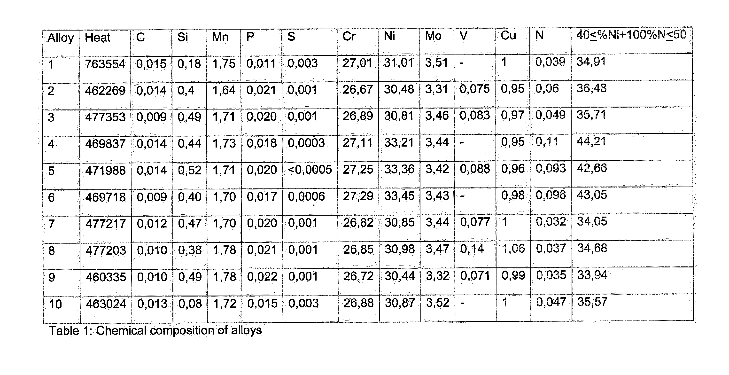
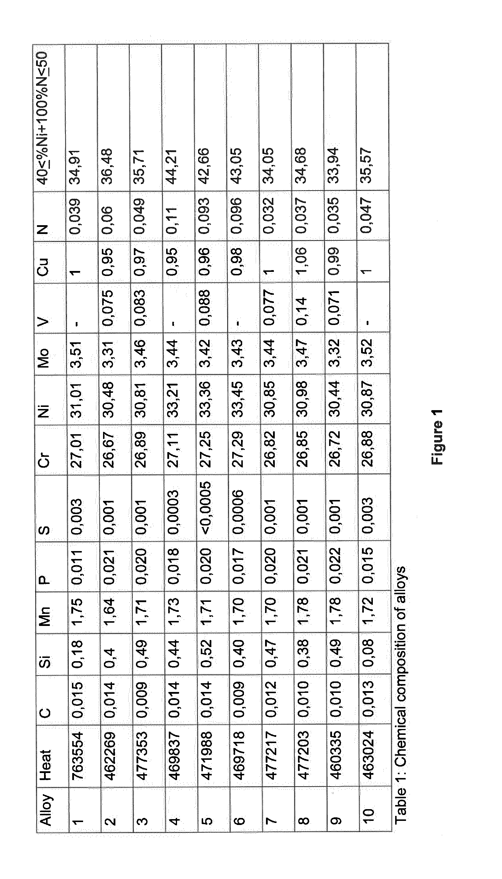
[0051]Following the inventive alloy will be described with reference to a concrete example.

[0052]Ten steel heats were prepared by conventional steel making methods. The composition of respective steel heat is shown in table 1. The conventional metallurgical process according to which the heats were prepared was as follows: Melting by AOD method-hot rolling-extruding-cold pilgring (cold deformation)-solution annealing-water quenching. The hollow bar material after the hot extruding was then cold pilgred with a cold deformation between 40 to 80%, followed by a solution annealing at a temperature between 1050 to 1180° C. depending on the dimension. The following table shows the details.

ColddeformationAlloyHeat(%)AnnealingCooling176355440-801050-1180 ° C. / 5-25 waterminutesquenching246226940-801050-1180 ° C. / 5-25waterminutesquenching3477353 40-801050-1180 ° C. / 5-25waterminutesquenching446983740-801050-1180 ° C. / 5-25waterminutesquenching547198840-801050-1180 ° C. / 5-25waterminutesquenching...


PUM

PropertyMeasurementUnit
Forceaaaaaaaaaa
Electric potential / voltageaaaaaaaaaa

Abstract

An austenitic alloy comprising (in weight %):
    • C: 0.01-0.05
    • Si: 0.05-0.80
    • Mn: 1.5-2
    • Cr: 26-34.5
    • Ni: 30-35
    • Mo: 3-4
    • Cu: 0.5-1.5
    • N: 0.05-0.15
    • V: <0.15
the balance being Fe and unavoidable impurities, wherein 40<% Ni+100*% N<50.

Description

TECHNICAL FIELD[0001]The present invention relates to an austenitic alloy according to the preamble of claim 1. The invention also relates to a component for a combustion plant comprising the inventive austenitic alloy.BACKGROUND[0002]Power generation based on the combustion of biomass is regarded both sustainable and carbon neutral and is becoming an increasingly important source of energy.[0003]A problem in biomass combustion is that the combustion products of the wide range of biomass fuels that are used are corrosive and may cause depositions on components in the biomass power plant. Especially exposed are superheaters, re-heaters and evaporators in biomass power plants, as well as in conventional steam boilers. A further problem in biomass power plants is that the materials in the components start to creep due to the high temperatures and the high pressures in the power plant. Today, biomass plants operate at a pressure of 150-200 bar and at a temperature of 500-550° C. In the ...

Claims


Application Information

Patent Timeline
IPC IPC(8): C22C30/02
CPCC21D2211/001C22C30/02C22C38/42C22C38/44C22C38/58C22C38/001C22C38/002C22C38/004C22C38/02C22C38/46C22C19/053C22C30/00F22B37/04
Inventor CHAI, GUOCAIHOGBERG, JANAKESSON, SOFIAFORSBERG, URBAN
Owner SANDVIK INTELLECTUAL PROPERTY AB
Why Eureka
Try Eureka