
Manufacturing method for forming a semiconductor structure

Active Publication Date: 2014-11-27
UNITED MICROELECTRONICS CORP
View PDF2 Cites 50 Cited by
  • Summary
  • Abstract
  • Description
  • Claims
  • Application Information

AI Technical Summary

Benefits of technology

The present patent invention involves a method for making a semiconductor device by using multiple layers of photography. This method helps to control the size of the contact, and can simultaneously form contacts that replace certain parts of the device, reducing the manufacturing steps. Overall, this method simplifies the process of creating semiconductor devices.

Problems solved by technology

In current fabricating processes, due to the limitations of the back end of the line (BEOL) process capacity, the yield of contact plugs with high aspect ratio (HAR) is relatively low and cannot reach the new requirements.
However, since the upper contact structure (M0) and the lower contact structure are formed in different steps, a barrier layer will exist between the upper contact structure (M0) and the lower contact structure, thereby affecting the conductivity of the contact.
Besides, the manufacturing process is too complex.

Method used


Image

  • Manufacturing method for forming a semiconductor structure
  • Manufacturing method for forming a semiconductor structure
  • Manufacturing method for forming a semiconductor structure

Examples


Embodiment Construction

[0012]To provide a better understanding of the present invention to users skilled in the technology of the present invention, preferred embodiments are detailed as follows. The preferred embodiments of the present invention are illustrated in the accompanying drawings with numbered elements to clarify the contents and effects to be achieved.

[0013]Please note that the figures are only for illustration and the figures may not be to scale. The scale may be further modified according to different design considerations. When referring to the words “up” or “down” that describe the relationship between components in the text, it is well known in the art and should be clearly understood that these words refer to relative positions that can be inverted to obtain a similar structure, and these structures should therefore not be precluded from the scope of the claims in the present invention.

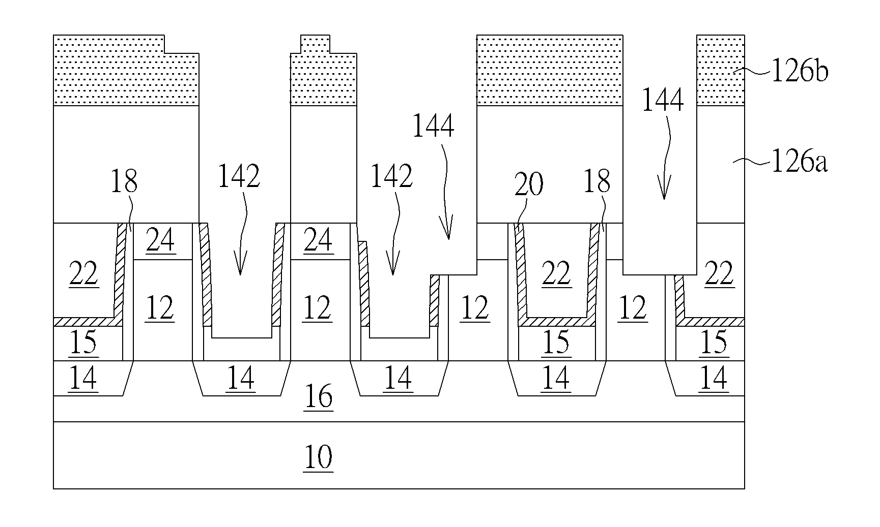
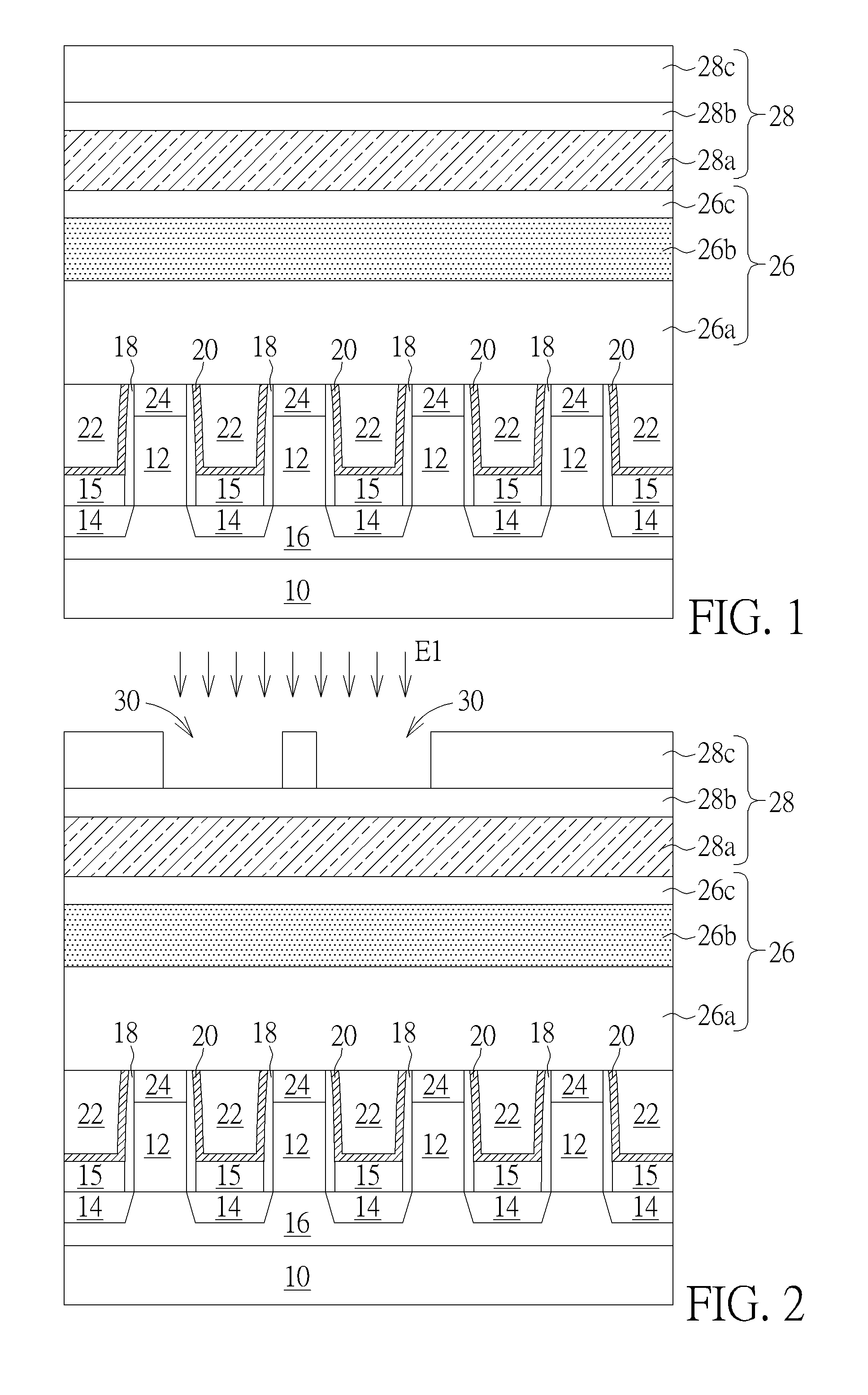
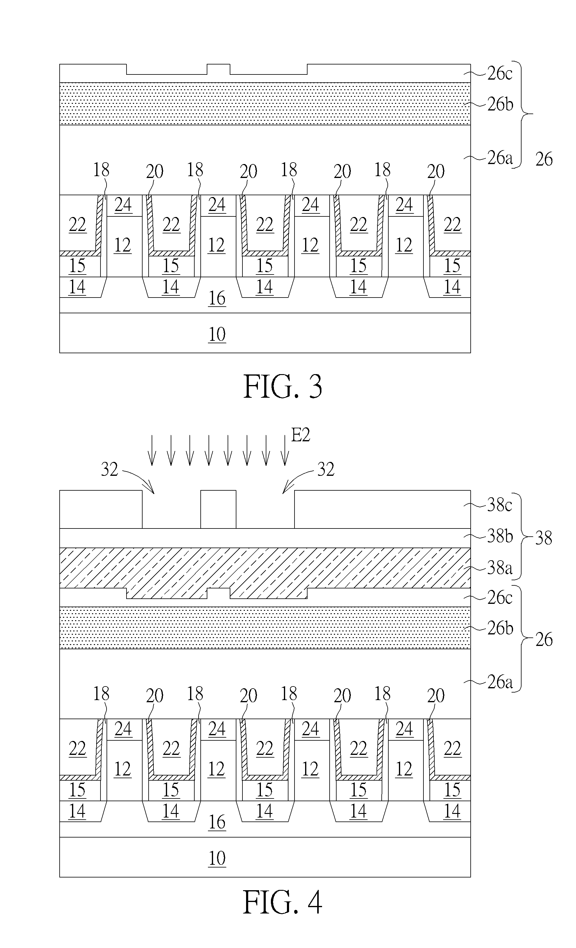
[0014]Please refer to FIGS. 1-9 are schematic diagrams illustrating a manufacturing method of the semic...


PUM


Abstract

The present invention provides a manufacturing method of a semiconductor device, at least containing the following steps: first, a substrate is provided, wherein a first dielectric layer is formed on the substrate, at least one metal gate is formed in the first dielectric layer and at least one source drain region (S / D region) is disposed on two sides of the metal gate, at least one first trench is then formed in the first dielectric layer, exposing parts of the S / D region. The manufacturing method for forming the first trench further includes performing a first photolithography process through a first photomask and performing a second photolithography process through a second photomask, and at least one second trench is formed in the first dielectric layer, exposing parts of the metal gate, and finally, a conductive layer is filled in each first trench and each second trench.

Description

BACKGROUND OF THE INVENTION[0001]1. Field of the Invention[0002]The present invention relates generally to semiconductor manufacturing process, and more specifically, to a method for forming a self aligned contact through a plurality of photolithography processes.[0003]2. Description of the Prior Art[0004]Along with the continuous miniaturization of the Integrated Circuits (IC), the line width of interconnections and the feature size of semiconductor devices have continuously shrunk. In general, discrete devices in integrated circuits are connected to each other through contact plugs (or contact slots) and interconnection structures, and their related fabrication methods have become an important matter in the next-generation semiconductor devices.[0005]In current fabricating processes, due to the limitations of the back end of the line (BEOL) process capacity, the yield of contact plugs with high aspect ratio (HAR) is relatively low and cannot reach the new requirements. In order to...

Claims


Application Information

Patent Timeline
IPC IPC(8): H01L21/768
CPCH01L21/76843H01L21/76816H01L21/76897H01L21/76895H01L23/485
Inventor CHEN, CHIEH-TELAI, YU-TSUNGCHEN, HSUAN-HSUCHANG, FENG-YIHUANG, CHIH-SENHUNG, CHING-WEN
Owner UNITED MICROELECTRONICS CORP
Learn More