Inverted-landing aircraft

a technology of inverted landing and aircraft, which is applied in the direction of vehicle position/course/altitude control, process and machine control, instruments, etc., can solve the problems of life-threatening visual exposure of the ground crew, the cost of such an aircraft is generally large in comparison to the cost of its payload,

Active Publication Date: 2014-11-27
AEROVIRONMENT INC
View PDF16 Cites 28 Cited by
  • Summary
  • Abstract
  • Description
  • Claims
  • Application Information

AI Technical Summary

Benefits of technology

[0012]Advantageously, the remote-control station is provided with an auto-land function that instructs the control system to operate the control surfaces such that the aircraft conducts an inverting maneuver in which the aircraft rotates from the upright orientation to the inverted orientation. In the inverted orientation, the aircraft can be landed without causing ground-cintact damage to delicate payloads that hang down from the aircraft when in the upright orientation.

Problems solved by technology

This configuration potentially puts the cameras and gimbals in harm's way during landing, particularly for payloads that are sensitive to high vibration and impact loads.
These aircraft do not typically have to take off and land in combat settings in which the visual exposure of the ground crew may be life threatening.
Moreover, the cost of such an aircraft is generally large in comparison to the cost of its payload, so the payload may be made structurally tolerant without significantly increasing the overall cost of the combined aircraft and payload.
Nevertheless, high resolution cameras of such structural integrity can be very expensive.
Given that smaller UAVs are significantly less expensive that large UAVs, providing a group of highly expensive cameras to a small UAV can add significantly to the cost of the aircraft.
While this may be effective to reduce the landing loads on the payload, the gimbal mechanism adds significant weight, and the need to fit it within the fuselage limits the size and shape of the payload.
Nevertheless, this involves surrendering flight control once a parachute is deployed, and thus greatly reduces the likelihood of a precise landing location.
Also, a parachute landing is also difficult to “call-off” if landing the aircraft is no longer desired, the landing trajectory is incorrect, or the landing site is no longer cleared.
Such issues could be extremely important in a situation where landing location is important, such as needing to land an aircraft on a rooftop or near a protected enclosure for ground personnel.

Method used


Image

  • Inverted-landing aircraft
  • Inverted-landing aircraft
  • Inverted-landing aircraft

Examples


Embodiment Construction

[0027]The invention summarized above and defined by the enumerated claims may be better understood by referring to the following detailed description, which should be read with the accompanying drawings. This detailed description of particular preferred embodiments of the invention, set out below to enable one to build and use particular implementations of the invention, is not intended to limit the enumerated claims, but rather, it is intended to provide particular examples of them. Furthermore, there is no intent to be bound by any expressed or implied theory presented in this application.

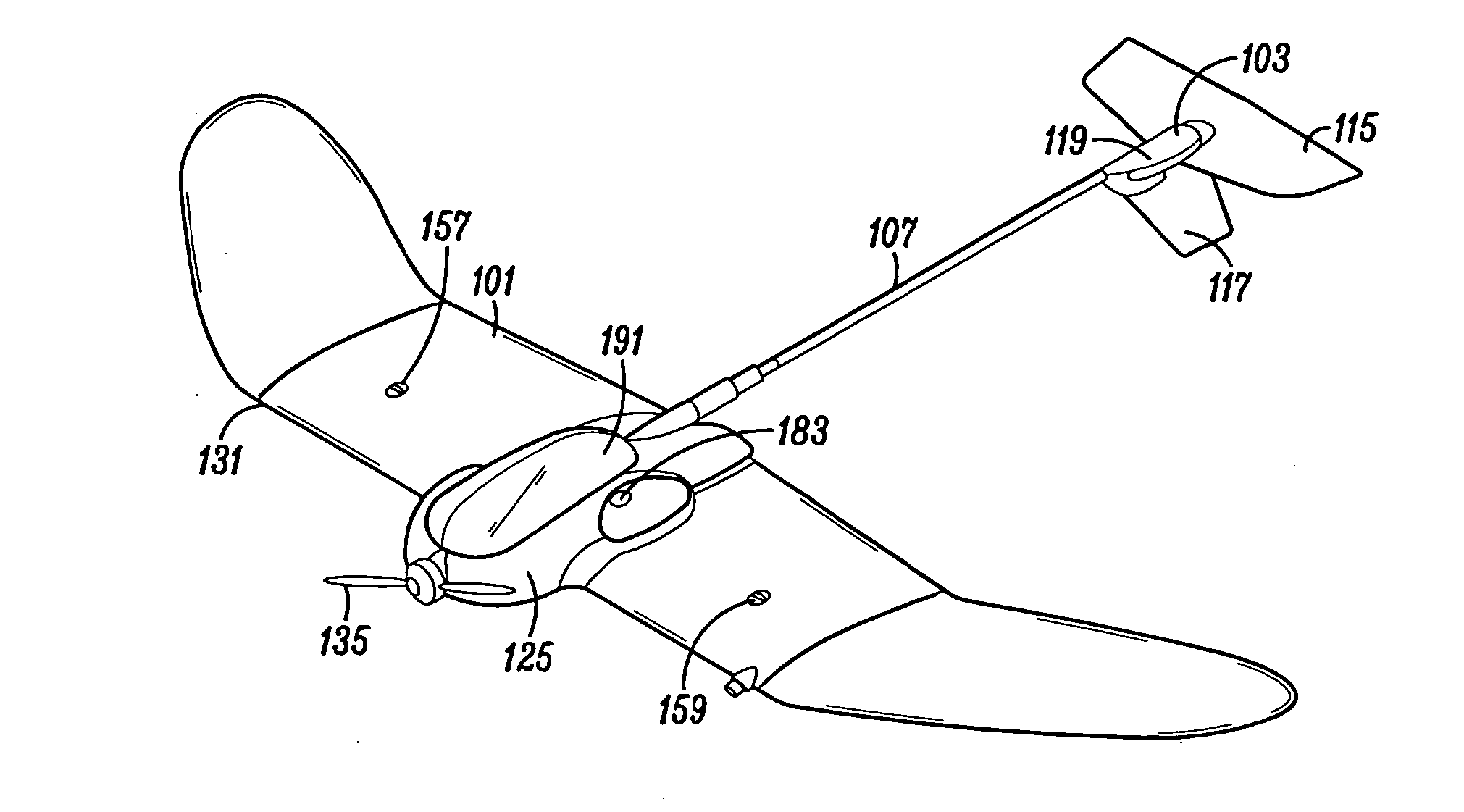
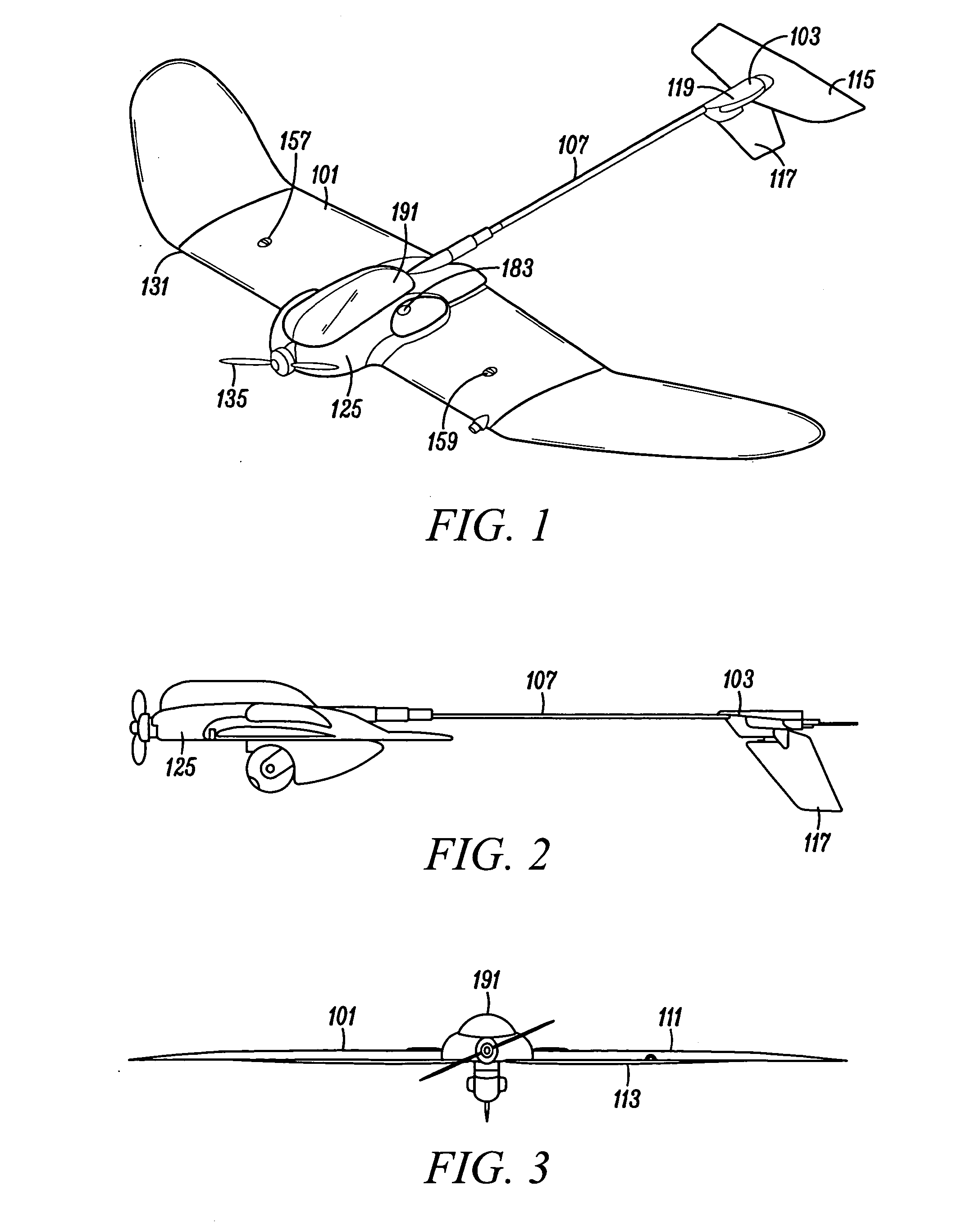
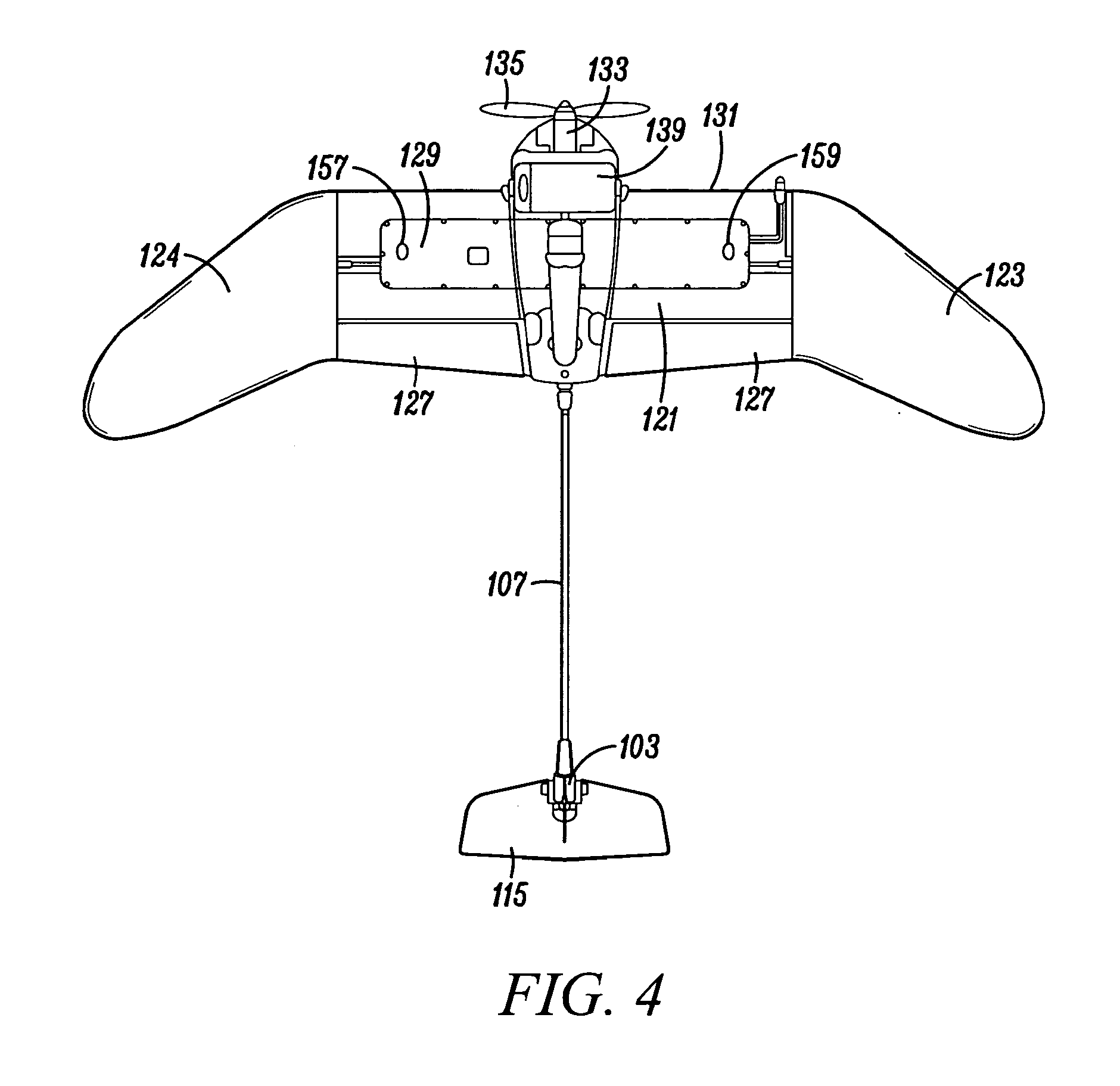
[0028]Typical embodiments of the present invention reside in an unmanned aerial vehicle (“UAV”) (i.e., an unmanned aircraft system) including a UAV configured to invert prior to landing, and then go in to a controllable stalled flight condition that provides for rapid but controlled descent.

[0029]UAV Aircraft

[0030]With reference to FIGS. 1 to 4, a first embodiment of an aircraft under the inventi...


PUM


Abstract

An aircraft defining an upright orientation and an inverted orientation, a ground station; and a control system for remotely controlling the flight of the aircraft. The ground station has an auto-land function that causes the aircraft to invert, stall, and controllably land in the inverted orientation to protect a payload and a rudder extending down from the aircraft. In the upright orientation, the ground station depicts the view from a first aircraft camera. When switching to the inverted orientation: (1) the ground station depicts the view from a second aircraft camera, (2) the aircraft switches the colors of red and green wing lights, extends the ailerons to act as inverted flaps, and (3) the control system adapts a ground station controller for the inverted orientation. The aircraft landing gear is an expanded polypropylene pad located above the wing when the aircraft is in the upright orientation.

Description

[0001]This application claims the benefit of U.S. Provisional Application No. 61 / 575,418, filed Aug. 19, 2011, which is incorporated herein by reference for all purposes.[0002]The present invention relates to an aircraft configured to fly in an upright orientation and land in an inverted orientation.BACKGROUND OF THE INVENTION[0003]Unmanned aerial vehicles (UAVs) have been developed for a large array of tasks. One such UAV task is for aerial reconnaissance. In UAV reconnaissance aircraft, a payload consisting of one or more cameras, and possibly one or more gimbaled supports for the cameras, might preferably extend below the fuselage and / or wing of the aircraft for maximum unimpeded viewing during flight. This configuration potentially puts the cameras and gimbals in harm's way during landing, particularly for payloads that are sensitive to high vibration and impact loads.[0004]Larger UAVs tend to have a significant range (distance they can travel), and are typically provided with s...

Claims


Application Information

Patent Timeline
Patent Type & Authority Applications(United States)
IPC IPC(8): B64C39/02G05D1/08
CPCB64C39/024G05D1/0816G05D1/0808G05D1/0676B64U10/25B64U30/10B64U2101/30B64U2201/20B64U70/00B64U50/13B64D47/08G01C5/005G05D1/0011
Inventor FISHER, CHRISTOPHER E.SZAREK, THOMAS ROBERTMCALLISTER, JUSTIN B.BELIK, PAVEL
Owner AEROVIRONMENT INC
Why Eureka
Try Eureka