Construction machine
a construction machine and construction technology, applied in the direction of electric control, speed sensing governors, instruments, etc., can solve the problems of easy air bubbles and cavitation, follow unsolved problems, and reduce the durability and life of hydraulic equipmen
- Summary
- Abstract
- Description
- Claims
- Application Information
AI Technical Summary
Benefits of technology
Problems solved by technology
Method used
Image
Examples
first embodiment
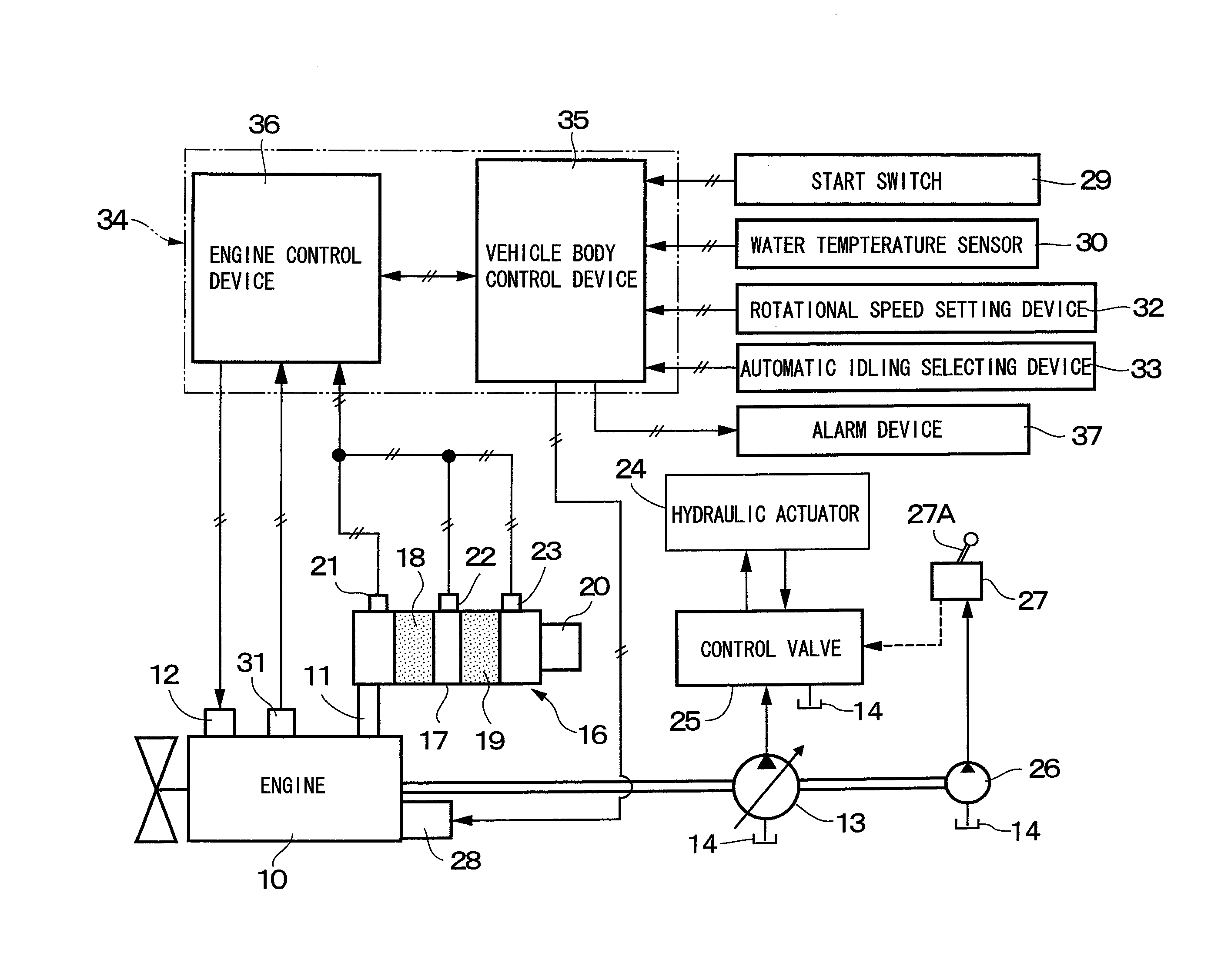
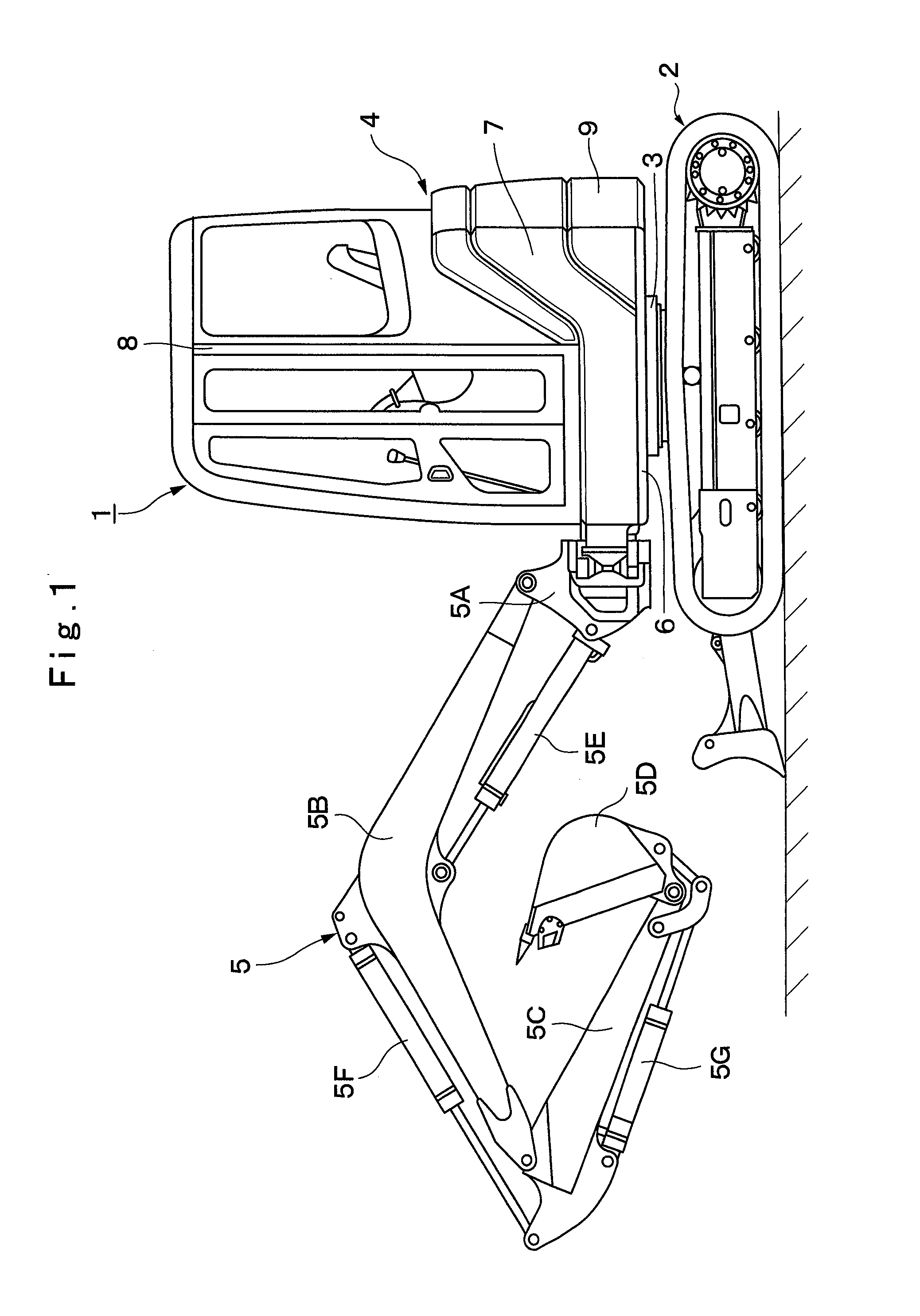
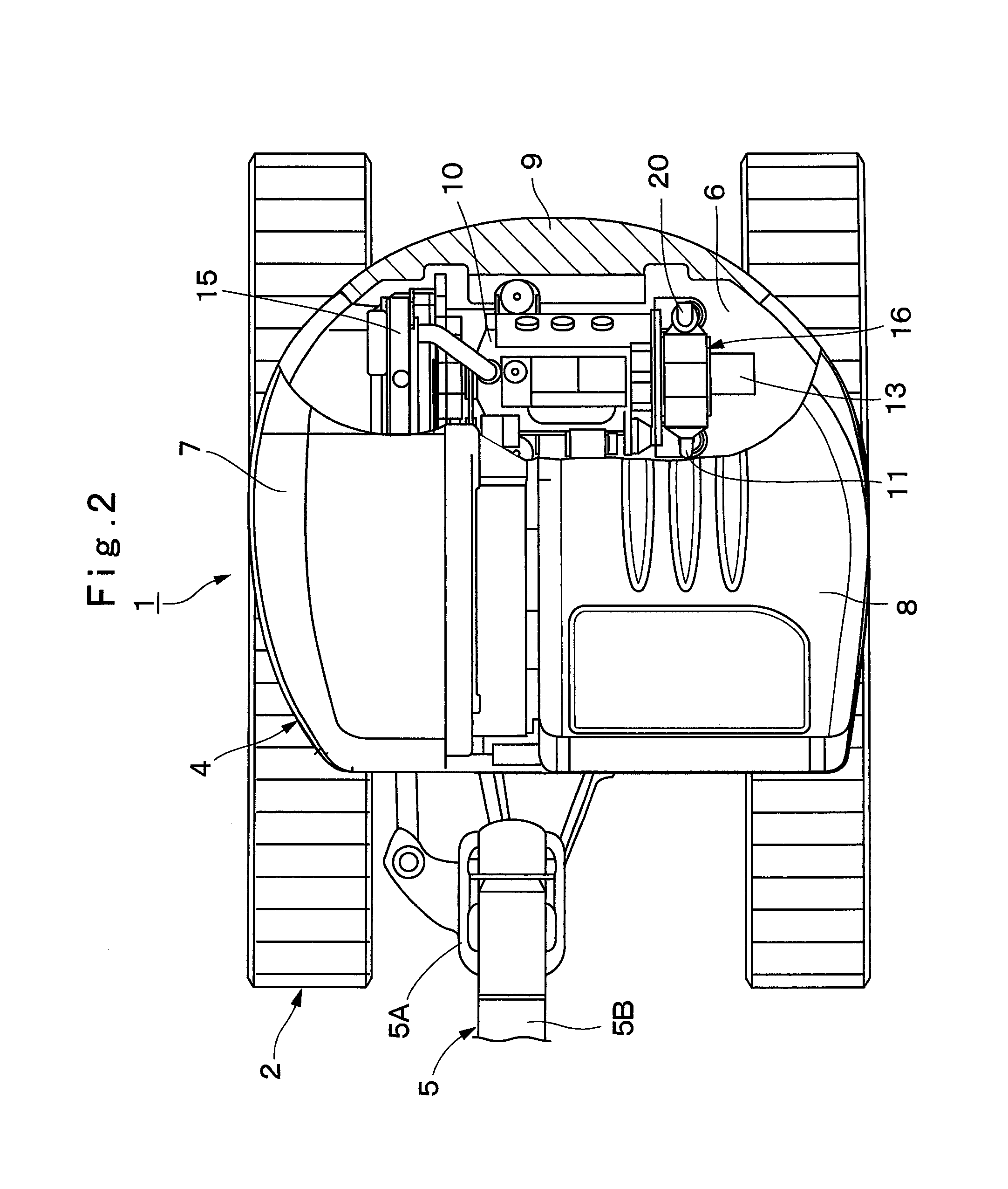
[0040]FIGS. 1 to 7 show a hydraulic excavator according to the present invention.
[0041]In the figures, designated at 1 is a small-sized hydraulic excavator used for an excavating work of earth and sand and the like, an earth removing work and the like. This hydraulic excavator 1 includes an automotive crawler-type lower traveling structure 2, an upper revolving structure 4 rotatably mounted on the lower traveling structure 2 through a revolving device 3 and constituting a vehicle body together with the lower traveling structure 2, and a working mechanism 5 provided capable of moving upward / downward on a front side of the upper revolving structure 4.
[0042]Here, the working mechanism 5 is constituted as a swing-post type working mechanism. This working mechanism 5 includes a swing post 5A, a boom 5B, an arm 5C, a bucket 5D as a working tool, a swing cylinder (not shown), a boom cylinder 5E, an arm cylinder 5F, and a bucket cylinder 5G. The upper revolving structure 4 is constructed wi...
second embodiment
[0101]In the second embodiment, assume that explanation will be made using an example in which, in the previous work using the hydraulic excavator 1, while the operator in the cab 8 rotates the dial 32A of the rotational speed setting device 32 to the position of the set value “Hi” indicated in FIG. 4, the engine 10 is stopped. As a result, if the engine 10 is to be newly started by the starter 28, it is presumed that the target rotational speed Nset of the engine 10 is set to the high idling rotational speed NHi shown in FIG. 5.
[0102]Here, the processing operation shown in FIG. 8 is started. Processing at Step 11 to Step 17 is performed similarly to Step 1 to Step 7 shown in FIG. 7 according to the above described first embodiment. Moreover, if it is determined to be “NO” at Step 13, the routine moves to Step 18, and the engine 10 is started similarly to Step 8 shown in FIG. 7. However, in the second embodiment, in processing at Step 19 subsequent to Step 18, the temporary target r...
third embodiment
[0126]It should be noted that, in the above described third embodiment, the case in which, when the engine 10 is newly started, the dial 32A of the rotational speed setting device 32 is rotated to the position of the set value “Hi”, the target rotational speed Nset of the engine 10 is set to the high idling rotational speed NHi is described as an example. However, the automatic recovery control by the present invention is not limited to that, and the automatic recovery control may be performed along characteristic lines 43 and 44 other than the characteristic line 42 shown in FIG. 10, for example.
[0127]That is, when the engine 10 is newly started, the dial 32A of the rotational speed setting device 32 might have been rotated to a position of a set value “Mh” of medium- to high-speed rotation exemplified in FIG. 4. As a result, the target rotational speed Nset of the engine 10 is set to a rotational speed NMh at a medium- to high-speed lower than the high idling rotational speed NHi ...
PUM
 Abstract
Description
Claims
Application Information
 - R&D
- Intellectual Property
- Life Sciences
- Materials
- Tech Scout
- Unparalleled Data Quality
- Higher Quality Content
- 60% Fewer Hallucinations
Browse by: Latest US Patents, China's latest patents, Technical Efficacy Thesaurus, Application Domain, Technology Topic, Popular Technical Reports.
© 2025 PatSnap. All rights reserved.Legal|Privacy policy|Modern Slavery Act Transparency Statement|Sitemap|About US| Contact US: help@patsnap.com


