
Electrical insulation system

a technology of electrical insulation and insulation system, applied in the direction of insulating conductors/cables, cables, insulated conductors, etc., can solve the problems of premature electrical failure of electric machines, poor heat conduction, and large machine siz

Active Publication Date: 2014-12-04
GENERAL ELECTRIC CO
View PDF15 Cites 12 Cited by
  • Summary
  • Abstract
  • Description
  • Claims
  • Application Information

AI Technical Summary

Benefits of technology

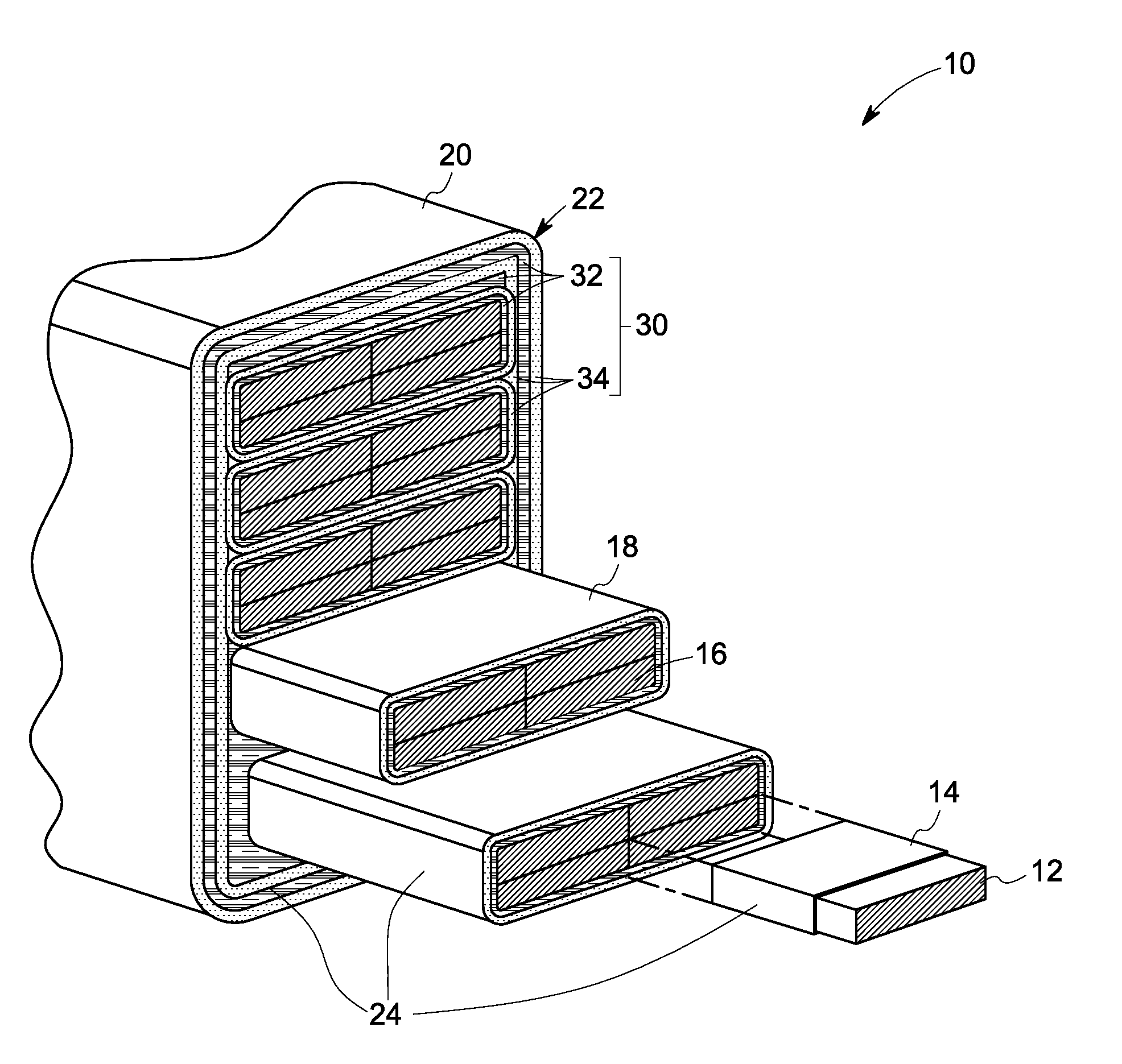
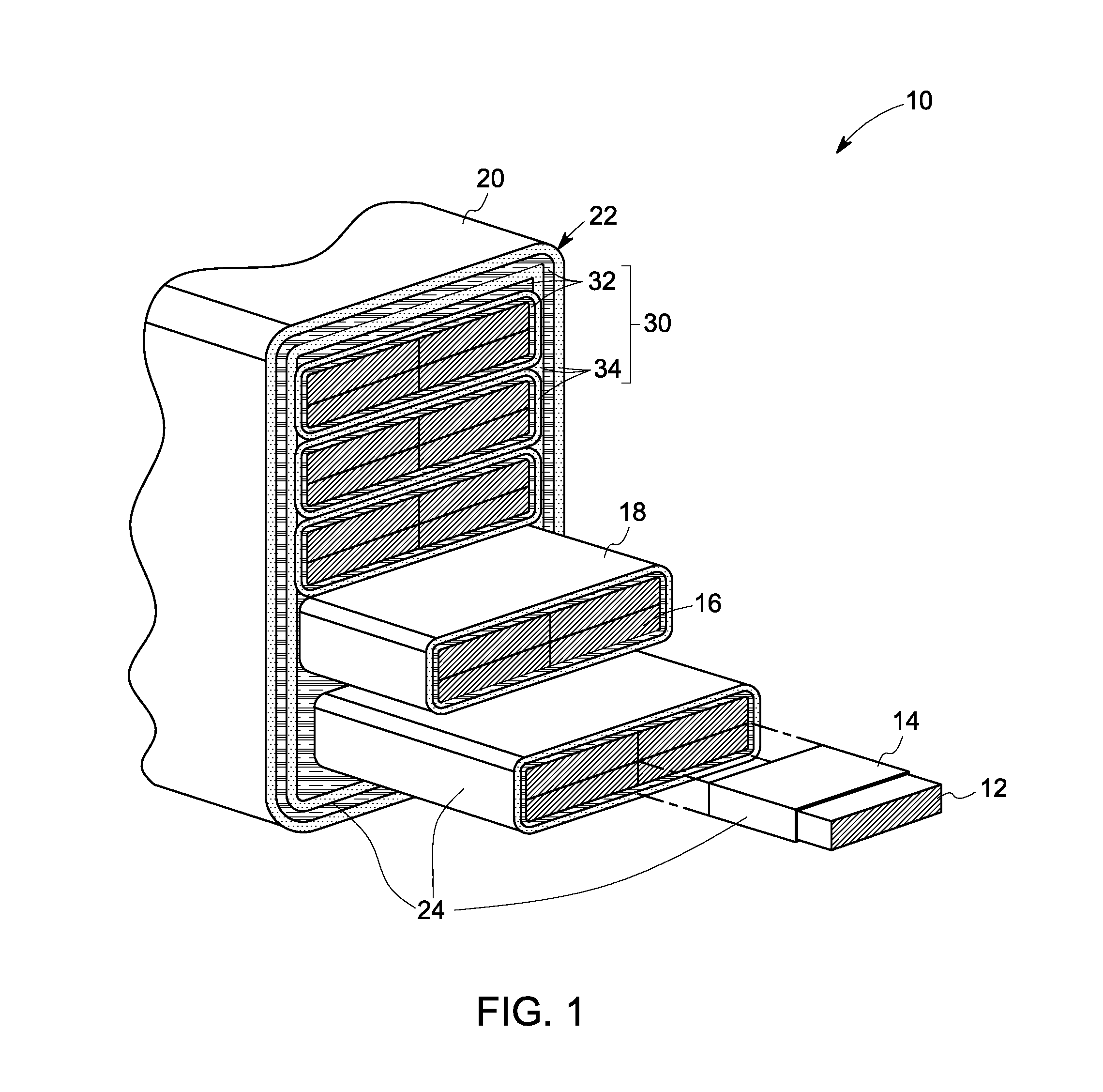
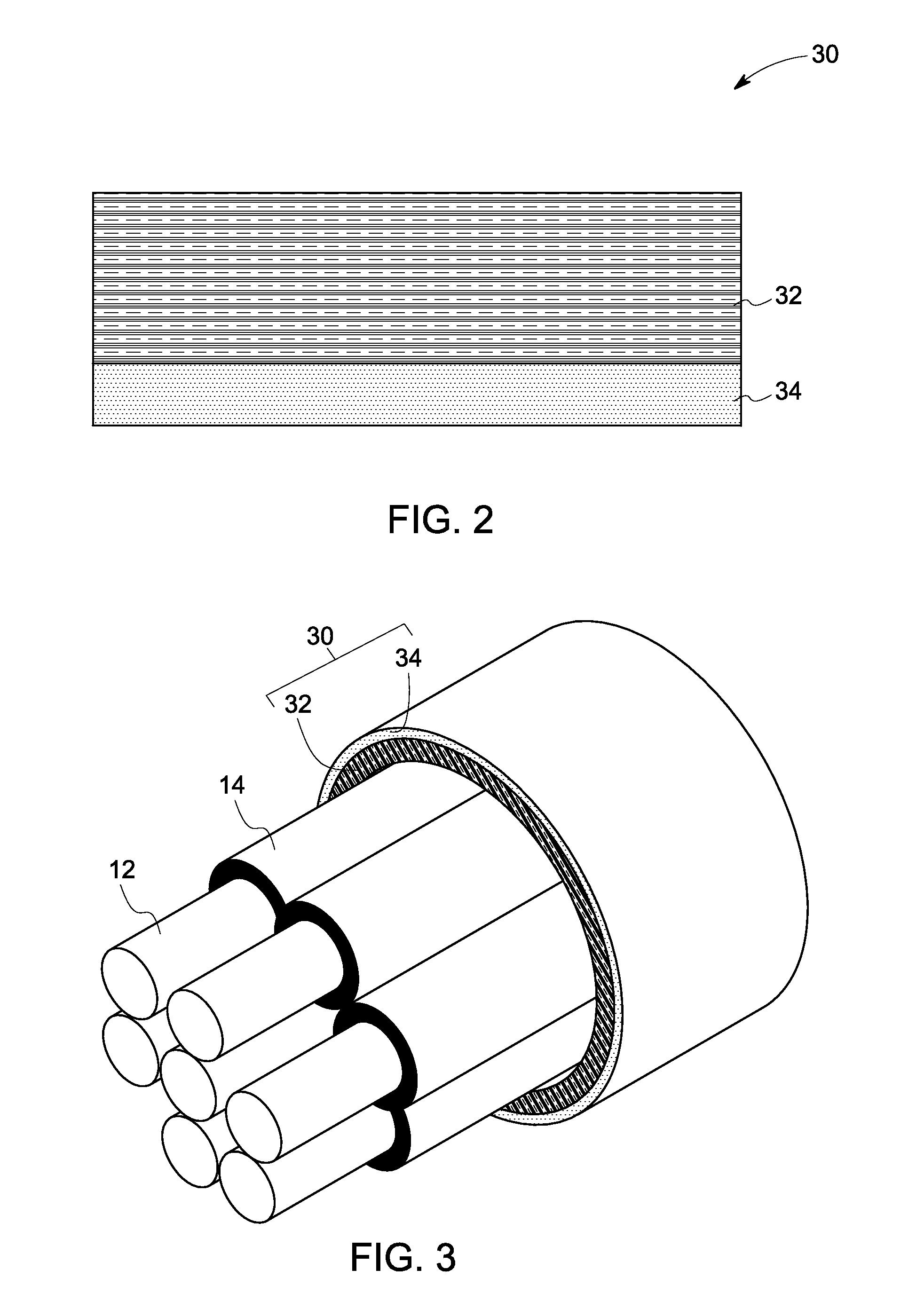
This patent describes a system that includes electrically conducting material and an insulation system. The insulation system includes a layered insulation tape with two layers. The first layer is made of mica paper and binder resin, while the second layer is made of a composite of layered nanoparticles in a polyetheretherketone (PEEK) matrix. The system also includes a vacuum impregnated resin that contains nanofillers. The insulation system is shaped as turn insulation and ground wall insulation for the electrically conducting material. The technical effect of this patent is to provide an improved insulation system that provides better protection against electrical arcing and can withstand higher temperatures.

Problems solved by technology

With increasing use of pulse width modulated (PWM) drives, electric machines experience premature electrical failure caused by higher electrical stress on winding insulation, due in part to uneven voltage distribution under high dV / dt conditions.
However, this can lead to large machine size and poor heat conduction.
However, microvoids may be created during the impregnation or curing of the epoxy resins, leading to poor thermal conduction and partial discharge.
Mica tapes and glass fibers may not have the mechanical stability required for the robust performance of the electrical machine.
However it can be deficient, in terms of long term voltage endurance, due to the poor corona resistance of polyester film.
Mica tape made of mica paper with fiberglass is known to have good long term voltage endurance performance, but can have poor taping quality and lower dielectric breakdown strength.
This is particularly suitable for resin-rich mica tape, for heat press or autoclave processes, but may not be good for mica tape that is used in vacuum pressure impregnated (VPI) machines, for high power applications.

Method used


Image

  • Electrical insulation system
  • Electrical insulation system
  • Electrical insulation system

Examples


examples

[0052]The following examples illustrate methods, materials and results, in accordance with specific embodiments, and as such should not be construed as imposing limitations upon the claims. All components are commercially available from common chemical suppliers.

[0053]The processability, manufacturability, dielectric capability, viability, and moisture and H2S / CO2 resistance of an exemplary insulation tape and nano-filled, global vacuum impregnated resin was tested for the application of a medium voltage rotating machine insulation.

[0054]A PEEK film (Aptiv™ 1000), mineral filled PEEK film (Aptiv™ 1102, Aptiv™ 1103), and a pure epoxy (class H resin, Epoxylite™, Von Roll™ 3407) with nanofillers (Al2O3, TiO2, SiO2), were used as samples for testing. The AC breakdown strength, dissipation factor, and pulse endurance of the pure epoxy vs. nano-filled epoxy; and PEEK film vs. mineral filled PEEK film, were compared. Epoxy curing characteristics, such as curing onset temperature, heat of r...


PUM

PropertyMeasurementUnit
Sizeaaaaaaaaaa
Particle sizeaaaaaaaaaa
Electrical conductoraaaaaaaaaa

Abstract

A system and a method are presented. The system includes an electrically conducting material and an electrical insulation system. The electrical insulation system includes a layered insulation tape that has a first layer and a second layer. The first layer includes a mica paper and a binder resin in a range from about 5 wt % to about 12 wt % of the insulation tape. The second layer includes a composite of layered nanoparticles dispersed in a polyetheretherketone (PEEK) matrix. The second layer laminates the first layer. The method includes attaching the first layer and the second layer with or without the addition of further resin; using the layered insulation tape as a turn insulation and ground wall insulation for an electrically conducting material; and impregnating the system with a nanofiller-incorporated resin by a vacuum pressure impregnation method, to form an insulation system within the system.

Description

BACKGROUND[0001]The invention relates generally to electrical insulation systems. More particularly, some embodiments of the invention relate to electrical insulation systems including multi-strand, multi-turn conductor winding insulation and ground wall insulation, in a medium or high voltage rotating machine.[0002]With the use of any electrical machines, there is a need to electrically insulate the conductors in the machines. The need for electrical insulation in the machines increases with higher operating voltages. With increasing use of pulse width modulated (PWM) drives, electric machines experience premature electrical failure caused by higher electrical stress on winding insulation, due in part to uneven voltage distribution under high dV / dt conditions. One way to address insulation deficiency is to increase insulation build. However, this can lead to large machine size and poor heat conduction. Thus, a better insulation system that can enable reduction of electrical machine...

Claims


Application Information

Patent Timeline
IPC IPC(8): H01B3/04H01B3/30H01B13/08
CPCH01B3/04H01B3/30H01B13/08H01F5/06H01F41/122H02K3/32H02K3/34H02K3/40H02K3/42H02K3/44Y10T428/251
Inventor YIN, WEIJUNZHANG, LILIDURANTAY, LIONELGRIGNARD, JEAN FRANCOIS
Owner GENERAL ELECTRIC CO
Learn More