Wireless Sensor for Rotating Elements

a technology of rotating elements and sensors, applied in the field of condition sensors, can solve problems such as catastrophic failures, high cost and time consumption of tasks, and wear and tear of machines

Active Publication Date: 2014-12-04
PURDUE RES FOUND INC
View PDF6 Cites 18 Cited by
  • Summary
  • Abstract
  • Description
  • Claims
  • Application Information

AI Technical Summary

Benefits of technology

[0013]A second embodiment is a system for measuring a physical characteristic of mechanical face seal that includes a permanent magnet and a magnetic sensor. The permanent magnet is affixed to a structure proximate to a bearing surface of the mechanical face seal. The permanent magnet has

Problems solved by technology

During their operating lifetime, machines undergo wear and tear due to friction and aging.
This wear and tear is primarily located in bearings, seals, etc., and if not detected can lead to catastrophic failures.
This task is expensive and time consuming.
In many industrial applications, the bearing temperatures rise beyond the maximum operating temperature of the lubricants, leading to evaporation.
Accordingly, the possibility of unusually high temperatures operation increases the need for frequent disassembly and inspection, thereby increasing maintenance costs.
The sensors are coupled to the outer race because of the difficulties of connecting circuits and sensors to a rotating element.
One drawback to this monitoring method, however, is that it has been shown that the outer race temperature is not reliable indicator of bearing temperature.
As a result, the measured temperature is not always truly reflective of the internal elements of the bearing.
While thi

Method used


Image

  • Wireless Sensor for Rotating Elements
  • Wireless Sensor for Rotating Elements
  • Wireless Sensor for Rotating Elements

Examples


Embodiment Construction

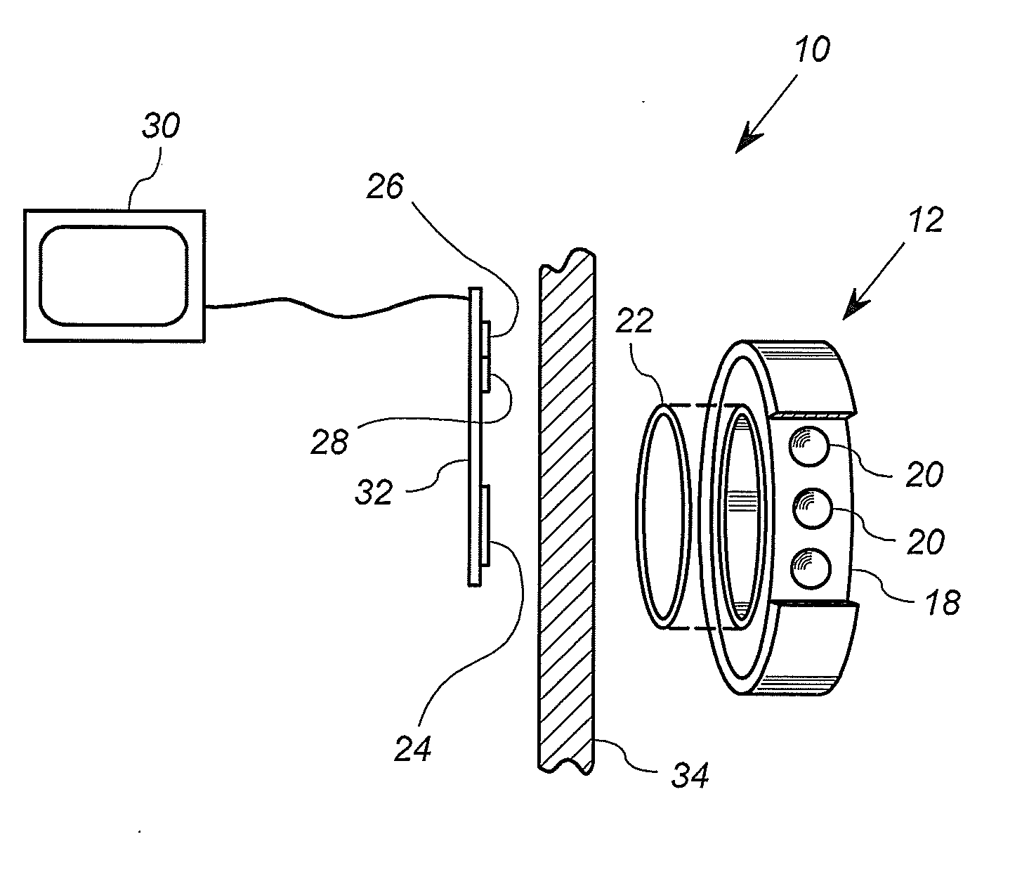
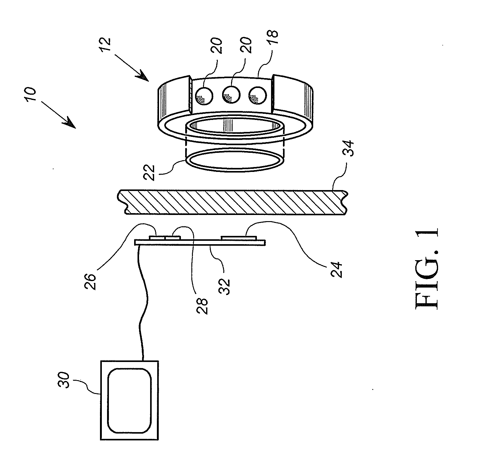
[0034]FIG. 1 shows an arrangement 10 for measuring at least one physical characteristic of a bearing 12. The arrangement 10 includes the bearing 12, a measurement system 11 and a display 30. The measurement system 11 includes a permanent magnet 22, a magnetic sensor 24, a processing circuit 26, and a memory 28. In general, the permanent magnet 22 and magnetic sensor 22, 24 cooperate to form a wireless sensor 22, 24. In the arrangement 10 of FIG. 1, the bearing 12 is part of a larger structure or machine, not shown, but which includes a metallic wall or device 34 interposed between the magnetic sensor 24 and the bearing 12. In general, the metallic wall or device 34 provides structural, protective, or other function to the bearing 12 and / or to the larger structure to which the bearing 12 is mounted.

[0035]In this embodiment, the bearing 12 is a ball bearing that includes an inner race 14, and outer race 16, a cage 18 and a plurality of balls 20. In general, the cage 18 and the plurali...


PUM


Abstract

A system for measuring a physical characteristic of a bearing includes a permanent magnet and a magnetic sensor. The permanent magnetic is coupled to at least a portion of a bearing, and has a magnetic field that changes as a function of the physical characteristic. For example, the permanent magnet has a magnetic characteristic that changes as a function of temperature. The magnetic sensor is operably disposed in a magnetic field sensing relationship with the permanent magnet, and is configured to generate a voltage signal and/or current signal corresponding to a sensed magnetic field.

Description

FIELD OF THE INVENTION[0001]The present invention relates to condition sensors, and more particularly, to sensors used for diagnostics, conditioning monitoring and / or damage detection in rotating elements.BACKGROUND OF THE INVENTION[0002]The implementation of damage identification systems in machines is defined as condition monitoring. During their operating lifetime, machines undergo wear and tear due to friction and aging. This wear and tear is primarily located in bearings, seals, etc., and if not detected can lead to catastrophic failures. One such example is bearings in aircraft. To check reliability of rotating components, bearing assemblies are disassembled and thoroughly inspected for degradation at periodic maintenance intervals. This task is expensive and time consuming.[0003]In many industrial applications, the bearing temperatures rise beyond the maximum operating temperature of the lubricants, leading to evaporation. In such conditions, the bearing failure can be hasten...

Claims


Application Information

Patent Timeline
IPC IPC(8): G01K7/36G01N25/72
CPCG01N25/72G01K7/36G01K7/38F16J15/3492G01K13/08G01R33/038G01R33/07
Inventor GUPTA, LOKESH ANILKUMARPEROULIS, DIMITRIOS
Owner PURDUE RES FOUND INC
Why Eureka
Try Eureka