Riblet Foil and Method for Producing Same

Inactive Publication Date: 2014-12-04
EADS DEUT GMBH
View PDF3 Cites 22 Cited by
  • Summary
  • Abstract
  • Description
  • Claims
  • Application Information

AI Technical Summary

Benefits of technology

[0025]In a further embodiment, the reference mold is configured as a roller. This facilitates a continuous production of the riblet foil according to the invention.
[0026]Advantageously, the thickness of the riblet foil is adjustable by means of the rotational speed of the roller. When the rotational speed is low, thicknesses of, for example, 400 μm are achieved. When, on the other hand, the riblet foil is to be thin, for example 200 μm, the rotation

Problems solved by technology

However, structured plastic foils that have been used to date lack mechanical durability and suffer from degradation of the plastic foil as well as of the glue by which these foils are to adhere to the aircraft.
Degradation effects can even cause the plastic foils to become detached while in operation.
However, such a direct application of a structure or texture by means of casting method or by removal-machining methods (structure generation by a laser

Method used


Image

  • Riblet Foil and Method for Producing Same
  • Riblet Foil and Method for Producing Same
  • Riblet Foil and Method for Producing Same

Examples


Example

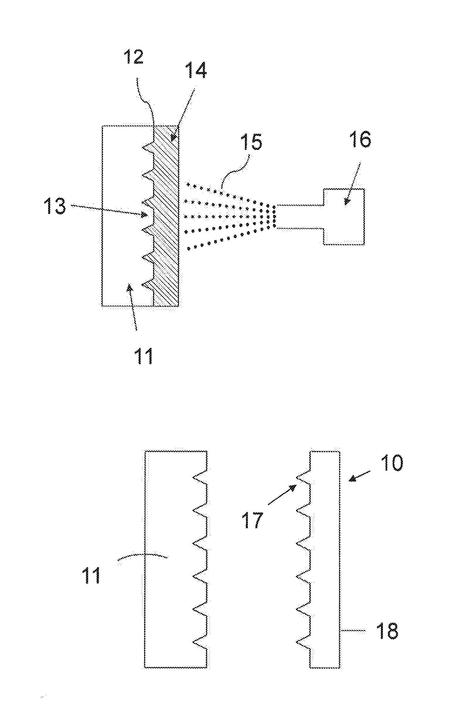
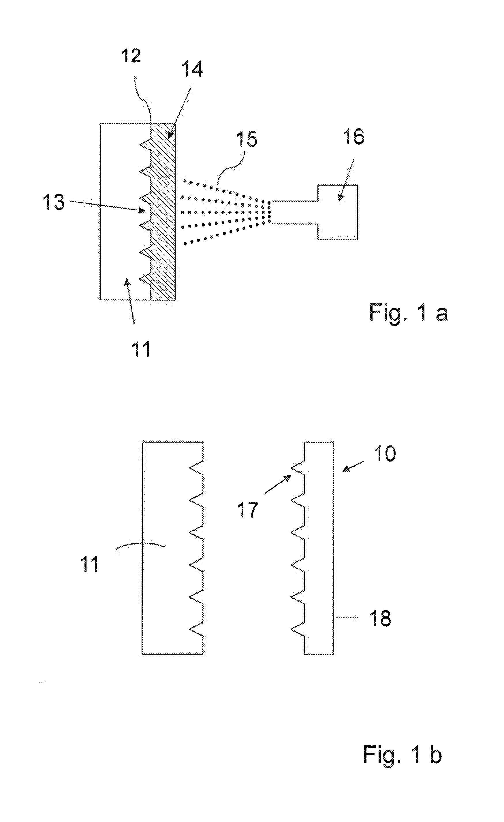
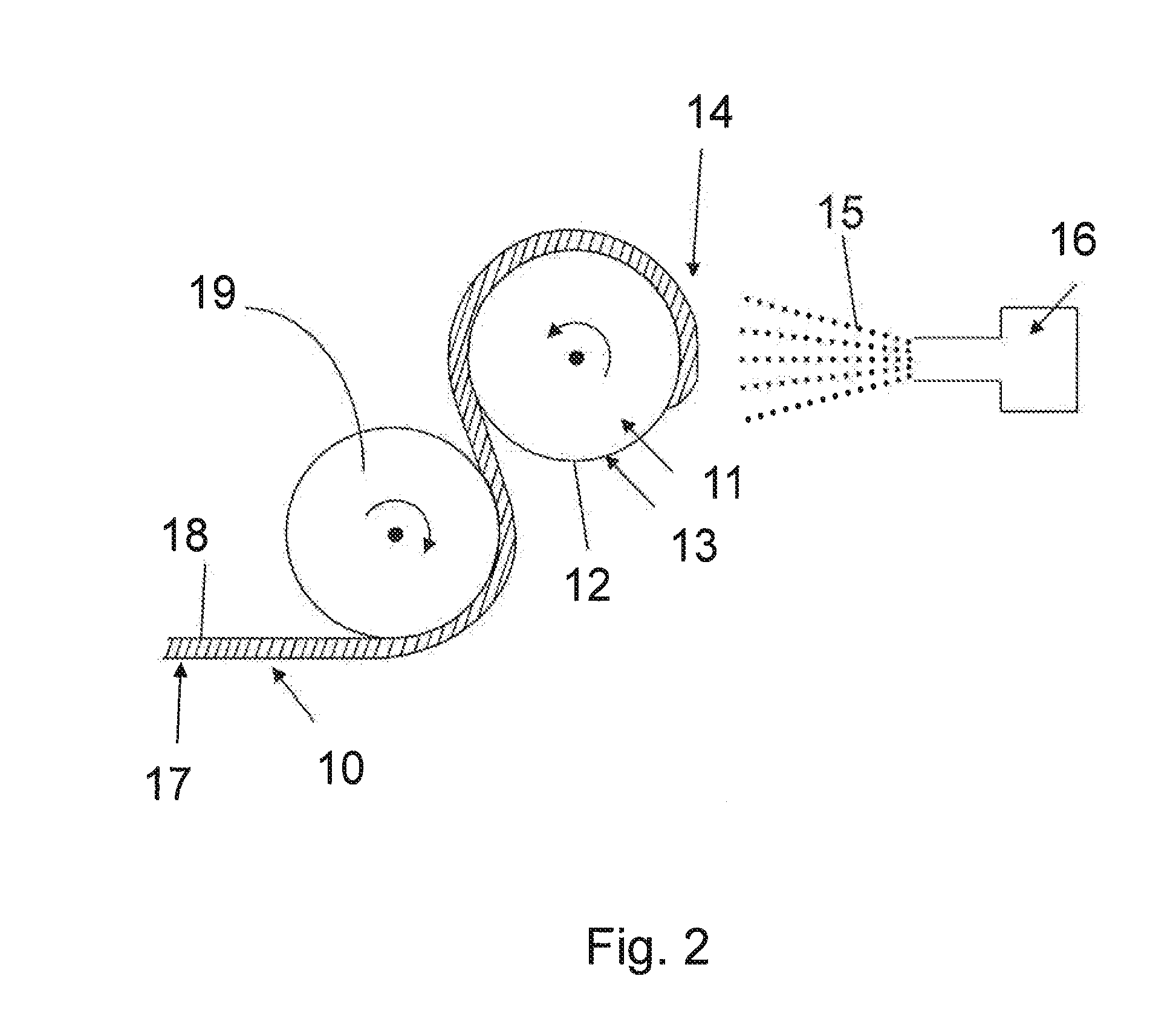
[0032]FIG. 1a is a sketch-type depiction of a riblet foil. A reference mold 11 includes an area 12 and a riblet structure 13. Using a coater system 16, metallic particles 15 of a metallic powder are accelerated to a high speed in the direction toward the area 12. Due to the impact, the metallic particles 15 become deformed and combine to form a metallic material. A continuous spraying action of metallic particles 15 against the area 12 results in a layer-type buildup of a layered portion 14. When the thickness of the layered portion 14 has reached the thickness that is required for the application the spray-on action of metal powder is complete.

[0033]In this embodiment, the coater system 16 is a system for cold gas spraying. A carrier gas is compressed and accelerated by relaxation of the same inside a nozzle to a speed that is below the speed of sound of the carrier gas. The metallic powder is injected into the gas jet. The carrier gas has a temperature that is below the temperatur...


PUM

PropertyMeasurementUnit
Thicknessaaaaaaaaaa
Structureaaaaaaaaaa
Speedaaaaaaaaaa

Abstract

A method for producing a layer-type buildup of riblet foil involves applying a metal powder is to a reference mold, which has a female mold of a riblet structure, in such a manner that a metallic material is formed. The layered portion applied in this manner is then detached, thereby forming a riblet foil having a riblet structure.

Description

FIELD OF THE INVENTION[0001]Exemplary embodiments of the present invention relate to a riblet foil and to a method for producing same. In particular, the riblet foil is made of metallic material and composed by way of layering said material onto a reference mold. The riblet foil has a riblet structure that reduces air resistance.BACKGROUND OF THE INVENTION[0002]Lowering fuel consumption and reducing carbon dioxide / nitrogen oxide (CO2 / NOx) emissions are important objectives to be met, particularly by the aviation and automotive industries. Aside from light construction modalities to achieve weight reductions and improvements to the efficiency of the drive systems, reducing air resistance constitutes one essential component in achieving these goals.[0003]Methods for producing surfaces that reduce the resistance to air flow are known in the art. It has been known for a long time, and, moreover, it has been proven in oil channel experiments, that, by providing solid surfaces with suitab...

Claims


Application Information

Patent Timeline
IPC IPC(8): B22F3/00B22F3/18B22F3/115
CPCB22F3/00B22F3/18B22F3/115B22F7/02
Inventor GAMMEL, FRANZROHR, OLIVER
Owner EADS DEUT GMBH
Why Eureka
Try Eureka