Battery Pack Including Fluid Resistant Over Mold

a battery pack and fluid-resistant technology, applied in secondary cell servicing/maintenance, battery packs, cell components, etc., can solve the problems of reducing the possibility of electrical communication between different conductors or mechanical components such as heat sinks, structural hardware, and mounting hardware, so as to increase the output voltage increase the amp-hour rating of the battery pack, and increase the output capacity and storage capacity of the battery pack

Active Publication Date: 2014-12-04
A123 SYSTEMS LLC
View PDF8 Cites 16 Cited by
  • Summary
  • Abstract
  • Description
  • Claims
  • Application Information

AI Technical Summary

Benefits of technology

[0002]Vehicle battery packs may include a plurality of battery cells combined in series and / or in parallel to supply power to propel a vehicle. Battery cells that are combined in series increase output voltage of the battery pack while battery cells that are combined in parallel increase the amp-hour rating of the battery pack. Individual battery cells within the battery pack may from time to time output a voltage that is different from other battery cells of the battery pack. Additionally, the charge storage capacity of some battery cells within the battery pack may be greater or less than the charge storage capacity of other battery cells within the battery cell pack. However, the output capacity and storage capacity of a battery pack may be increased when all battery cells within a battery pack are operated at substantially the same level of charge.

Problems solved by technology

However, the possibility of battery pack degradation may increase if battery cell charge is routed to a charge monitoring and charge balancing board that is remote from the individual battery cells.
Further, the possibility of battery pack degradation may increase when the battery pack is liquid cooled or if liquid enters the battery pack unintentionally.
The over mold may provide and / or maintain separation between conductors, and it may also reduce the possibility of electrical communication between different conductors or mechanical components such as heat sinks, structural hardware, mounting hardware, and housings that could be referenced to another potential, ground for example.

Method used


Image

  • Battery Pack Including Fluid Resistant Over Mold
  • Battery Pack Including Fluid Resistant Over Mold
  • Battery Pack Including Fluid Resistant Over Mold

Examples


Embodiment Construction

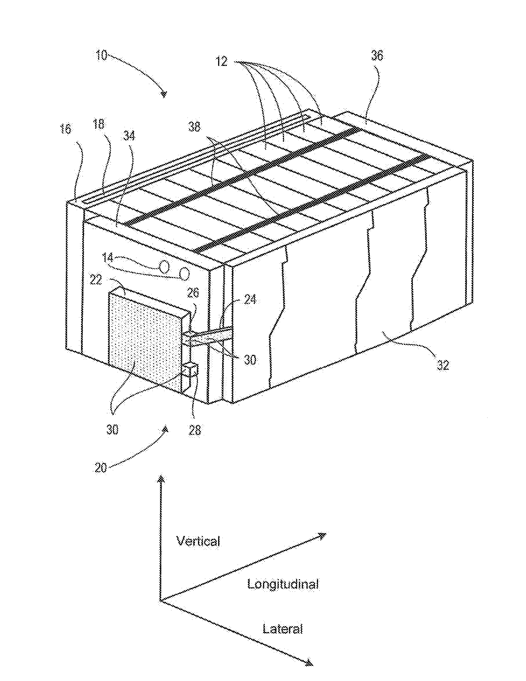
[0017]The present description is related to a battery pack having electrical circuitry at least partially encapsulated via a fluid resistant over mold. The over mold protects the electrical circuitry from moisture and other external elements which may degrade the battery pack.

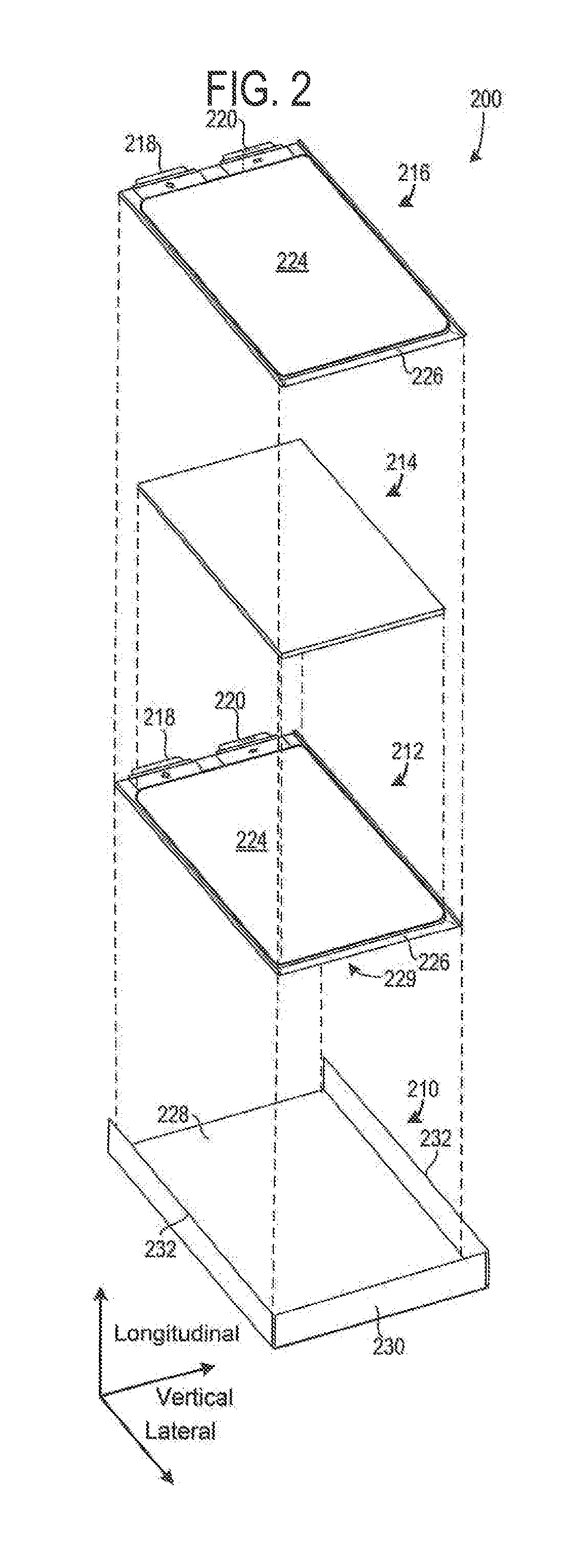
[0018]FIG. 1 illustrates a battery pack and FIG. 2 illustrates a non-aqueous electrolyte battery cell that may be included in the battery pack shown in FIG. 1. FIG. 3 illustrates a side view of the battery pack shown in FIG. 1. FIG. 4 shows a schematic depiction of components in the group of conductors included in the battery pack shown in FIG. 1. FIG. 5 shows an example printed circuit board and groups of conductors that may be included in the battery pack shown in FIG. 1. FIGS. 6 and 7 show example bus bars and conductors that may be included in the battery pack shown in FIG. 1. FIG. 8 shows an example wiring harness that may be included in the battery pack shown in FIG. 1.

[0019]FIG. 1 shows an exploded view ...


PUM

PropertyMeasurementUnit
pressureaaaaaaaaaa
heataaaaaaaaaa
threshold voltageaaaaaaaaaa

Abstract

A battery pack for supplying energy to propel a vehicle is disclosed. In one example, a battery pack includes a thermoplastic over mold for providing resistance to liquid is disclosed. The battery pack may have increased resistance to battery pack degradation.

Description

TECHNICAL FIELD[0001]The present description relates to reducing the possibility of degradation of a battery pack. In one example, the battery pack provides power to a vehicle and is liquid cooled.BACKGROUND AND SUMMARY[0002]Vehicle battery packs may include a plurality of battery cells combined in series and / or in parallel to supply power to propel a vehicle. Battery cells that are combined in series increase output voltage of the battery pack while battery cells that are combined in parallel increase the amp-hour rating of the battery pack. Individual battery cells within the battery pack may from time to time output a voltage that is different from other battery cells of the battery pack. Additionally, the charge storage capacity of some battery cells within the battery pack may be greater or less than the charge storage capacity of other battery cells within the battery cell pack. However, the output capacity and storage capacity of a battery pack may be increased when all batte...

Claims


Application Information

Patent Timeline
Patent Type & Authority Applications(United States)
IPC IPC(8): H01M10/613H01M50/211H01M50/284H01M50/296H01M50/298H01M50/569
CPCH01M10/5004H01M10/502H01M2220/20H01M2/10H01M10/5097H01M10/63H01M10/6554H01M10/647H01M2200/103H01M10/6568H01M2/1094H01M10/50H01M10/5077H01M10/5053H01M10/5032H01M10/482H01M10/5016H01M10/625H01M10/425H01M10/667H01M2010/4271Y02E60/10H01M50/24H01M50/284H01M50/296H01M50/569H01M50/211H01M50/298
Inventor CIACCIO, MICHAEL, P.
Owner A123 SYSTEMS LLC
Why Eureka
Try Eureka