

Aircraft powerplant
a power plant and module technology, applied in the direction of machines/engines, engine starters, transportation and packaging, etc., can solve the problems of reduced range and/or endurance time, performance deficit, and non-optimal propulsion system, and achieve the effect of reducing the level of returned radar signal and difficult detection
- Summary
- Abstract
- Description
- Claims
- Application Information
AI Technical Summary
Benefits of technology
Problems solved by technology
Method used
Image

Examples
first embodiment
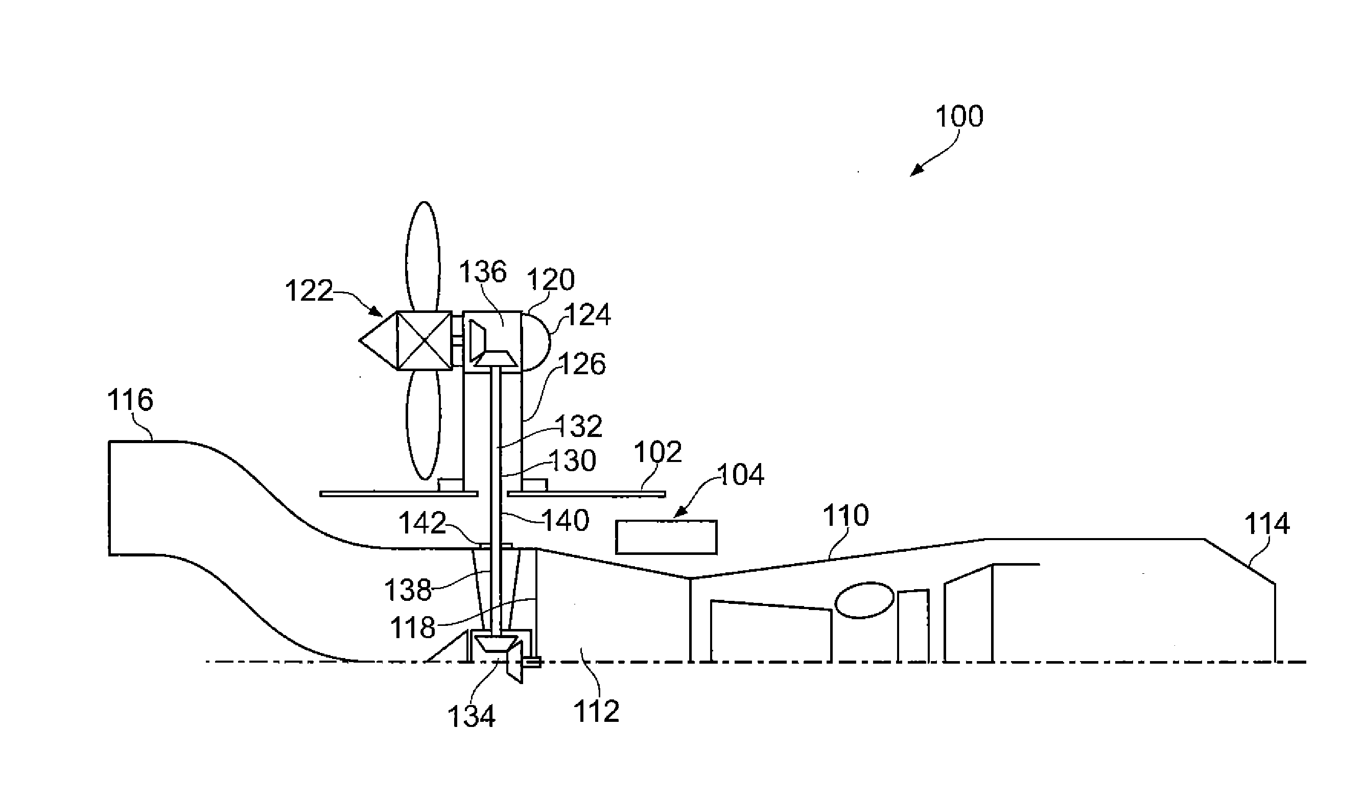
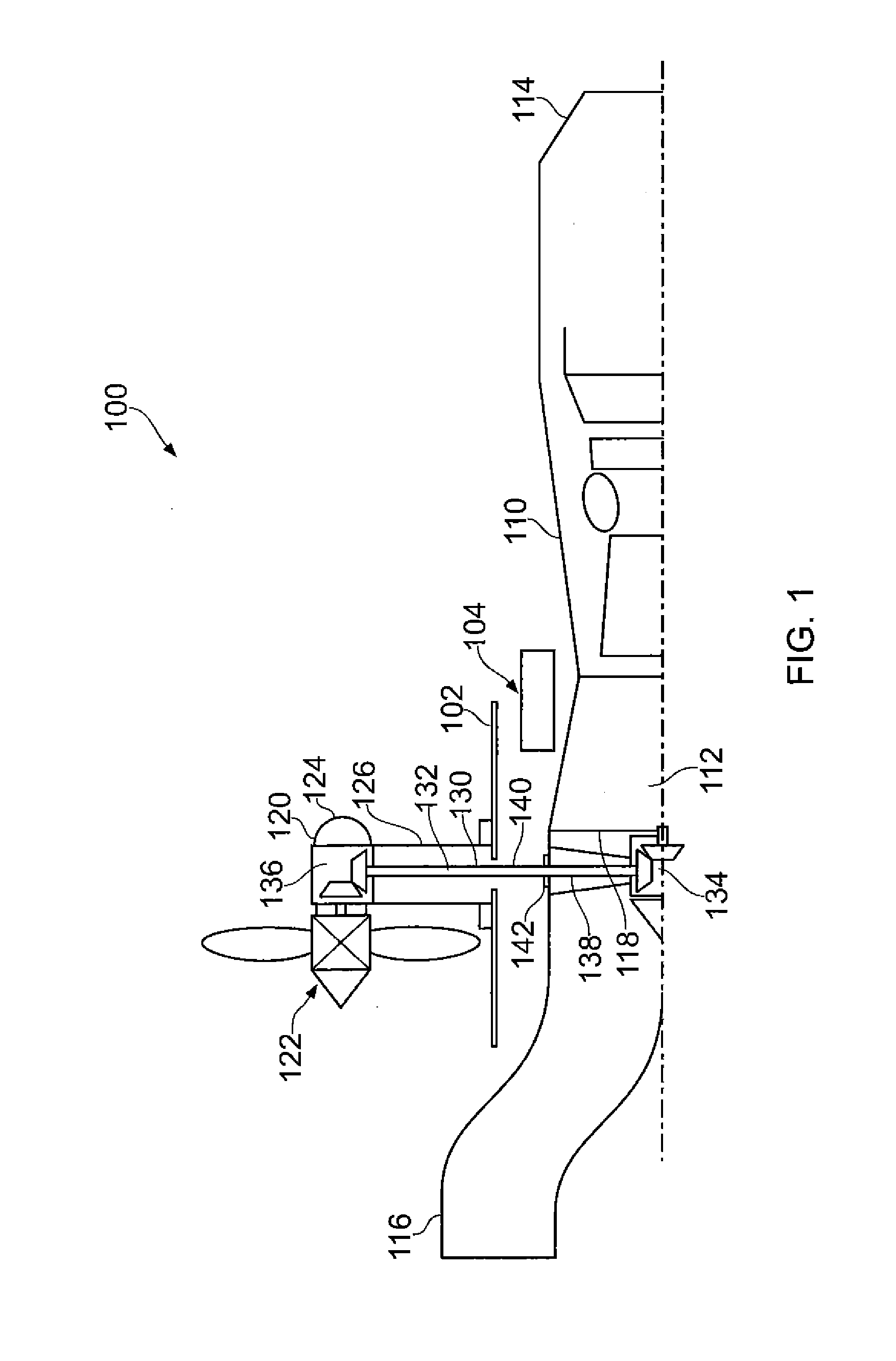
[0082]Referring to FIG. 1, a power plant according to the invention is designated generally by the reference numeral 100.
[0083]The power plant 100 comprises a core engine 110 housed within the airframe 102 of an aircraft (not shown), a secondary propulsion unit 120 housed in a nacelle 124, and a power transmission means 130.
[0084]The core engine 110 is a low bypass ratio turbofan engine. The core engine 110 is provided with a low pressure compressor 112 that has been designed with lower aerodynamic loading levels than the low pressure turbine from a conventional turbofan engine. This is necessary in order for the core engine 110 to efficiently produce the additional power required to drive the secondary propulsion unit 120.
[0085]The core engine 110 has an inlet face 118 being the frontmost surface of the core engine 110. In the present embodiment, this inlet face 118 is represented by the plane of the leading edges of the turbine spool 118. The inlet face 118 of the core engine 110 ...
second embodiment
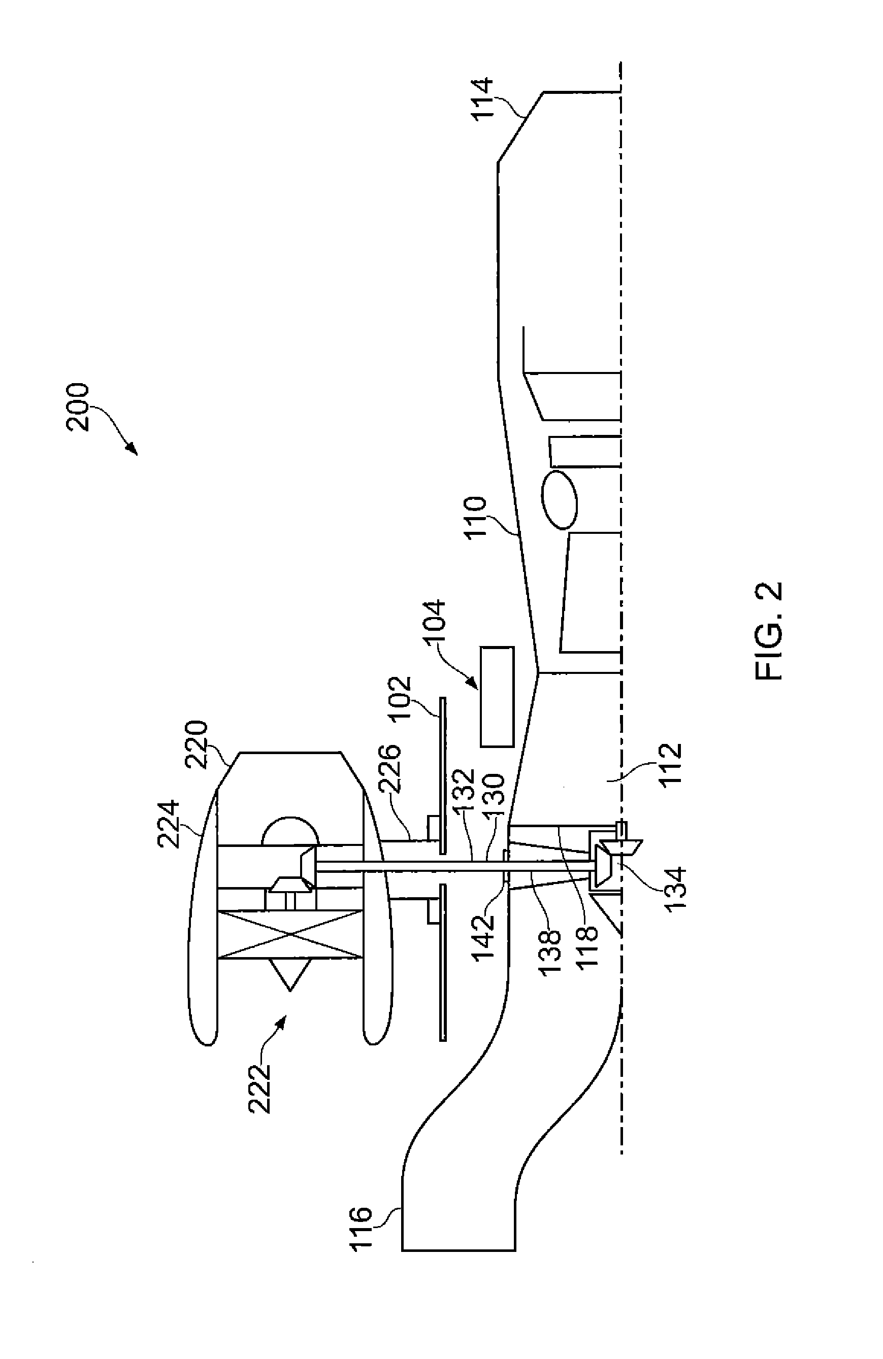
[0098]Referring to FIG. 2, a power plant according to the invention is designated generally by the reference numeral 200. Features of the power plant 200 which correspond to those of power plant 100 have been given corresponding reference numerals for ease of reference.
[0099]The power plant 200 comprises a core engine 110 housed within the airframe 102 of an aircraft (still not shown), a secondary propulsion unit 220 housed in a nacelle 124, and a power transmission means 130.
[0100]The secondary propulsion unit 220 differs from the secondary propulsion unit 120 in that the secondary propulsion unit 220 comprises a ducted fan 222 in place of the propeller 120.
[0101]In a similar manner to the first embodiment 100, the ducted fan 222 is housed within a nacelle 224 which is provided with a pylon 226 that is, in turn, removably attached to the airframe 102.
[0102]As mentioned above with respect to the first embodiment 100, the ducted fan 222 is provided with variable pitch blades. This al...
third embodiment
[0104]Referring to FIG. 3, a power plant according to the invention is designated generally by the reference numeral 300. Features of the power plant 300 which correspond to those of power plant 100 have been given corresponding reference numerals for ease of reference.
[0105]The power plant 300 comprises a core engine 310 housed within the airframe 102 of an aircraft (still not shown), a secondary propulsion unit 320 housed in a nacelle 324, and an electrical power transmission means 360.
[0106]The secondary propulsion unit 320 comprises a propeller 322 mounted on a nacelle 324 which in turn is fitted with a pylon 326. The propeller is directly connected to an electric motor 370 which is accommodated within the nacelle 322. The propeller 322 is a fixed pitch propeller.
[0107]Since the propeller 322 of the power plant 300 is driven independently of the core engine 310 via the electric motor 370 it is possible to realise some of the benefits of a variable pitch propeller. In particular,...
PUM
| Property | Measurement | Unit |
|---|---|---|
| Pressure | aaaaa | aaaaa |
| Power | aaaaa | aaaaa |
| Area | aaaaa | aaaaa |
Abstract
Description
Claims
Application Information