
Transmission control module

a technology of transmission control and control device, which is applied in the direction of electrical apparatus construction details, connector parts, electrical apparatus contruction details, etc., can solve the problems of difficult contact between the control device and the base carrier, the control device cannot be used for activating actuators, sensors, etc., and achieves the effect of reducing the total thickness of the printed circuit board, high bonding strength, and above the melting poin

Active Publication Date: 2014-12-11
ROBERT BOSCH GMBH
View PDF9 Cites 11 Cited by
  • Summary
  • Abstract
  • Description
  • Claims
  • Application Information

AI Technical Summary

Benefits of technology

The invention is a transmission control module that integrates a transmission control circuit into a compact and sealed way. The module includes a printed circuit board with conductor tracks and a carrier substrate that is inserted into a recess in the printed circuit board. The carrier substrate is connected to the printed circuit board using a molding compound that fills the recess and protects the circuit from transmission fluid. The molding compound is securely bonded to the printed circuit board and reduces the risk of fluid penetration. The module is designed to be easily integrated and protected from mechanical effects.

Problems solved by technology

However, without having a base carrier for the connection components connected to them, such control devices cannot be used for activating actuators, sensors, connector parts or servomotors of a transmission control.
The arrangement and contact-making of the control device with the base carrier is problematic because special measures are necessary to protect the electrical contact points between the control device and the base carrier from the transmission fluid and metallic swarf contained therein.

Method used


Image

  • Transmission control module
  • Transmission control module
  • Transmission control module

Examples


Embodiment Construction

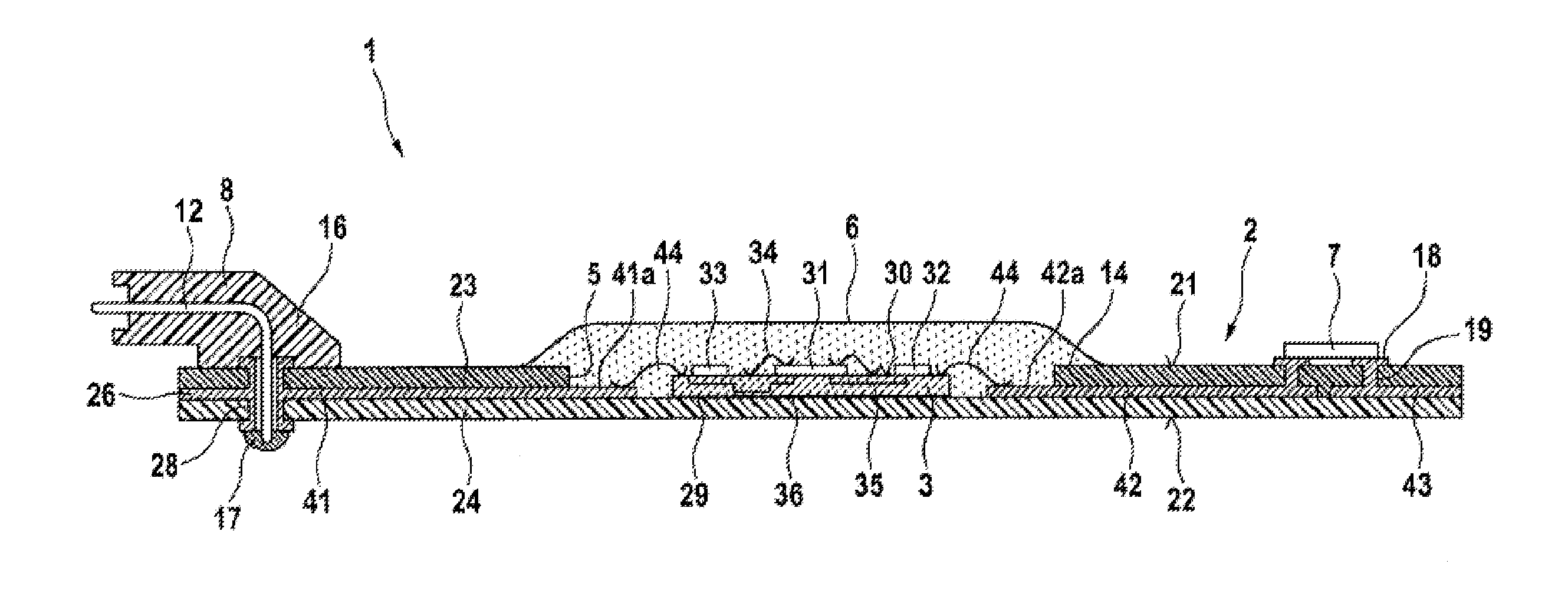
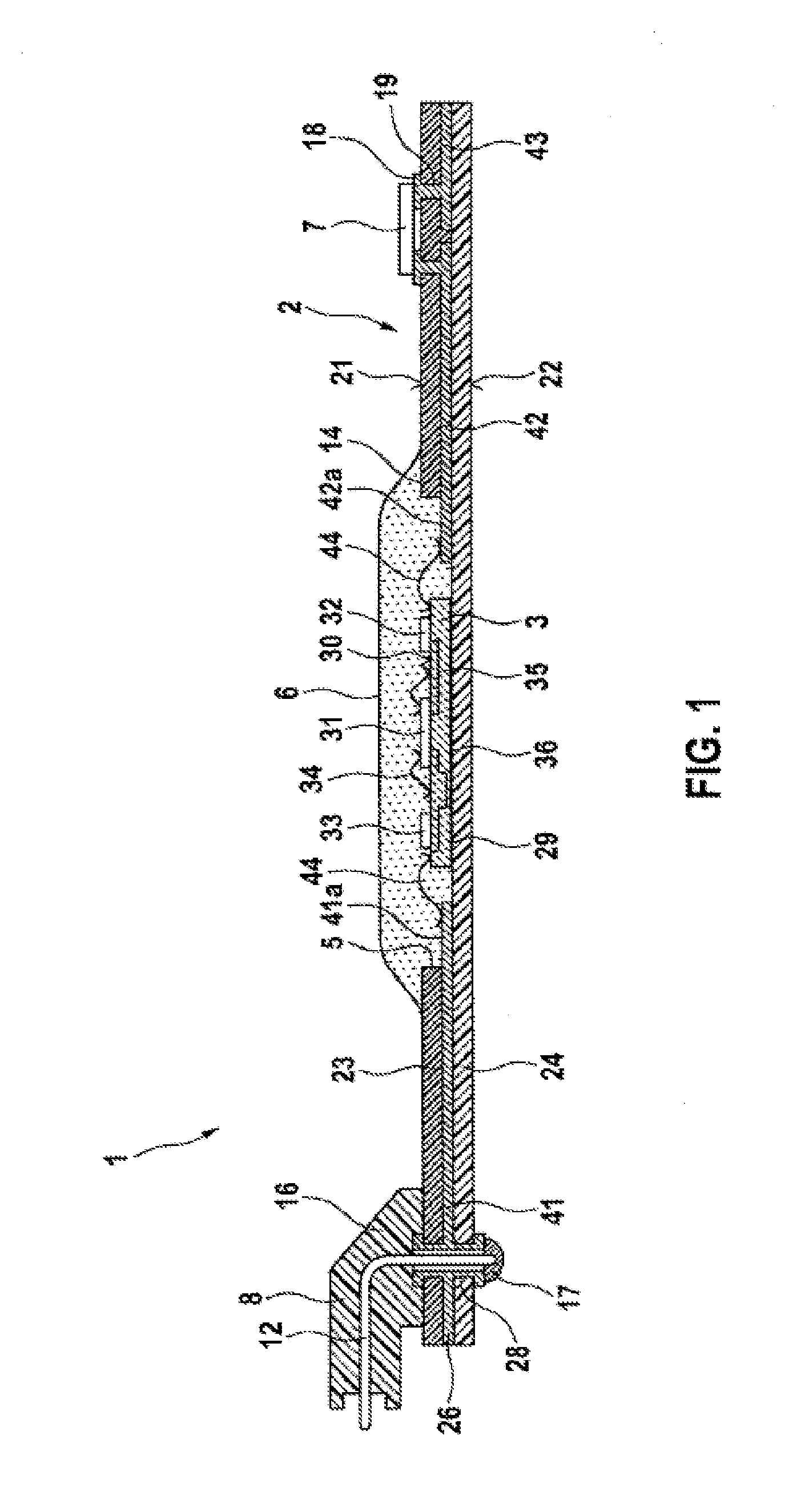
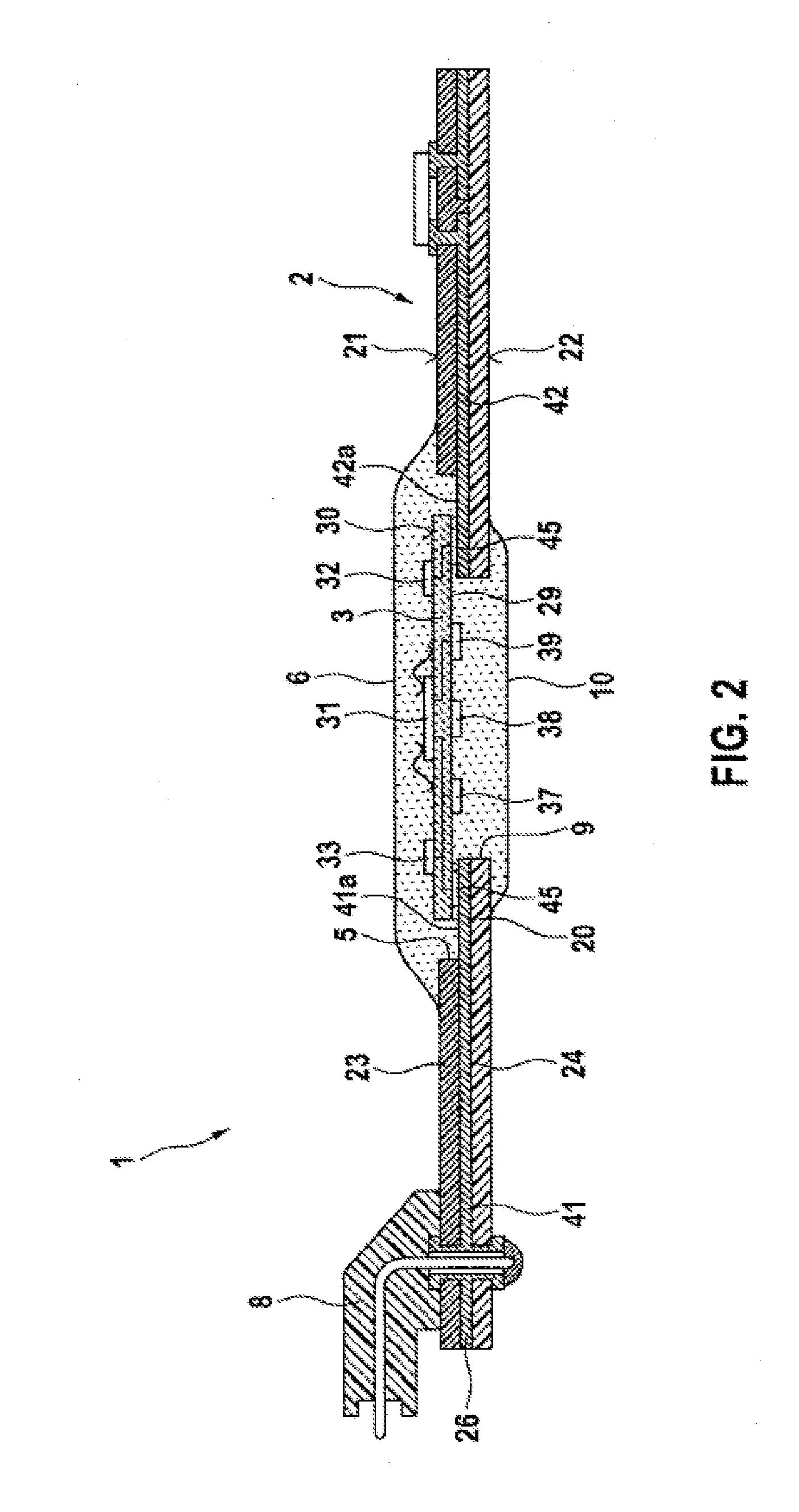
[0021]FIG. 1 shows a cross section through a first exemplary embodiment of a transmission control module 1 according to the invention, which may for example be installed in the automatic transmission of a motor vehicle. In principle, parts that are the same or very similar are provided with the same reference signs.

[0022]The transmission control module is intended to be at least partially or completely exposed to the transmission fluid (ATF) present in the transmission, and serves for activating adjusters and for reading sensors for the actuation of an automatic transmission. It goes without saying that the transmission control module may be adapted to the respectively required boundary conditions, such as the number and type of actuators, sensors and plug-in connections to be activated. The transmission control module may have a main body (not represented in the figures), which may for example be formed by a complex plastic part or a metallic carrier plate, to which a printed circu...


PUM


Abstract

A transmission control module includes a printed circuit board. The circuit board has conductor tracks routed on at least one layer of the circuit board and configured to electrically connect a carrier substrate to electrical components. The circuit board has an inner conductor track layer arranged between two insulating layers. A first outer insulating layer, at least on a first side of the circuit board, has a recess. Surfaces of conductor track sections of conductor tracks of the at least one inner conductor track layer are arranged at the bottom of the recess. The carrier substrate is inserted into the recess and makes electrical contact with the surfaces of the conductor track sections. The recess is filled with a moulding compound which covers at least the carrier substrate and the conductor track sections to protect the carrier substrate and the conductor track sections from transmission fluid.

Description

PRIOR ART[0001]The invention relates to a transmission control module with the features of the preamble of independent claim 1.[0002]In transmission control, there are known transmission control modules that have in addition to an electronic transmission control device a base carrier intended for making electrical contact with actuators, sensors, connector parts or actuating motors. It is known to use a printed circuit board as the base carrier of the electrical connection components. In this case, the electrical connections are preferably routed by way of inner layers of the printed circuit board. As a difference from classic control devices, which arrange a printed circuit board with an electronic control circuit arranged thereon within a closed metal housing, these transmission control modules use a conventional printed circuit board as the base carrier of the module, even outside the area protected by a housing. Such modules can be produced at particularly low cost because of th...

Claims


Application Information

Patent Timeline
IPC IPC(8): H05K1/18H05K1/02H05K1/14
CPCH05K1/185H05K1/144H05K1/181H05K1/0207H05K1/0298H01L23/3121H05K3/284H01L2224/32225H01L2224/48227H01L2224/73265H01L2924/19107H05K1/141H05K1/183H01L23/367H01L23/3677H01L23/49572H01L23/4985H01L24/73H01L2924/181H05K5/0082H05K7/20854H01L2924/00012
Inventor MEIER, THOMASMUELLER-VOGT, INGO
Owner ROBERT BOSCH GMBH
Learn More