Integrated Photonics Waveguide Grating Coupler

a waveguide and waveguide technology, applied in the field of integrated photonics, can solve the problems of difficult elimination, inability to achieve high-performance mode-size convertors between single-mode optical fibers, and inability to meet the requirements of integrated circuits, so as to achieve good miniaturization of the photonics integrated circuit and sacrifice the coupling efficiency of the grating

Active Publication Date: 2014-12-11
UNIV GENT +1
View PDF8 Cites 36 Cited by
  • Summary
  • Abstract
  • Description
  • Claims
  • Application Information

AI Technical Summary

Benefits of technology

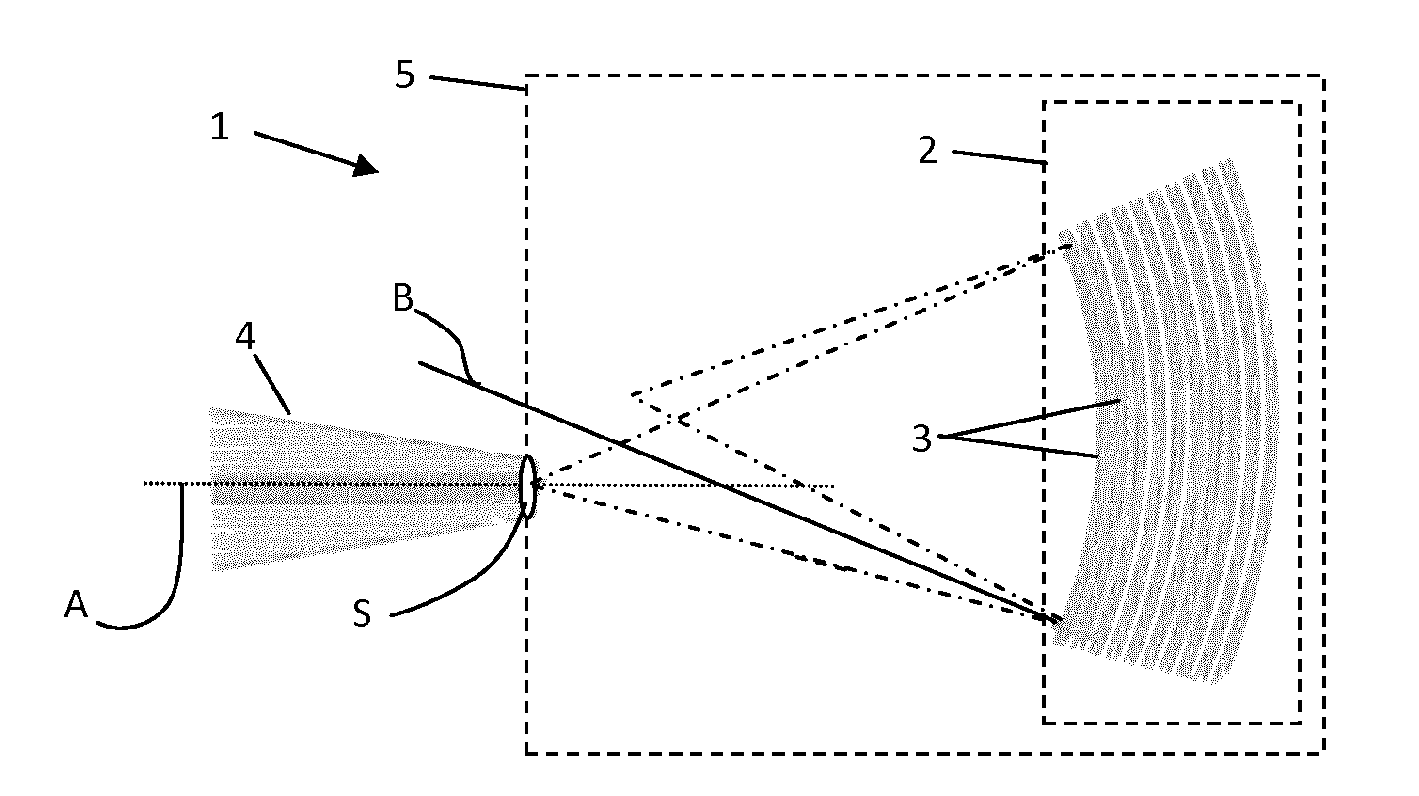
[0009]It is an advantage of grating couplers according to embodiments of the present invention that back-reflections, e.g. second order reflections and Fresnel reflections, may be focused away from the entrance waveguide in the integrated waveguide.
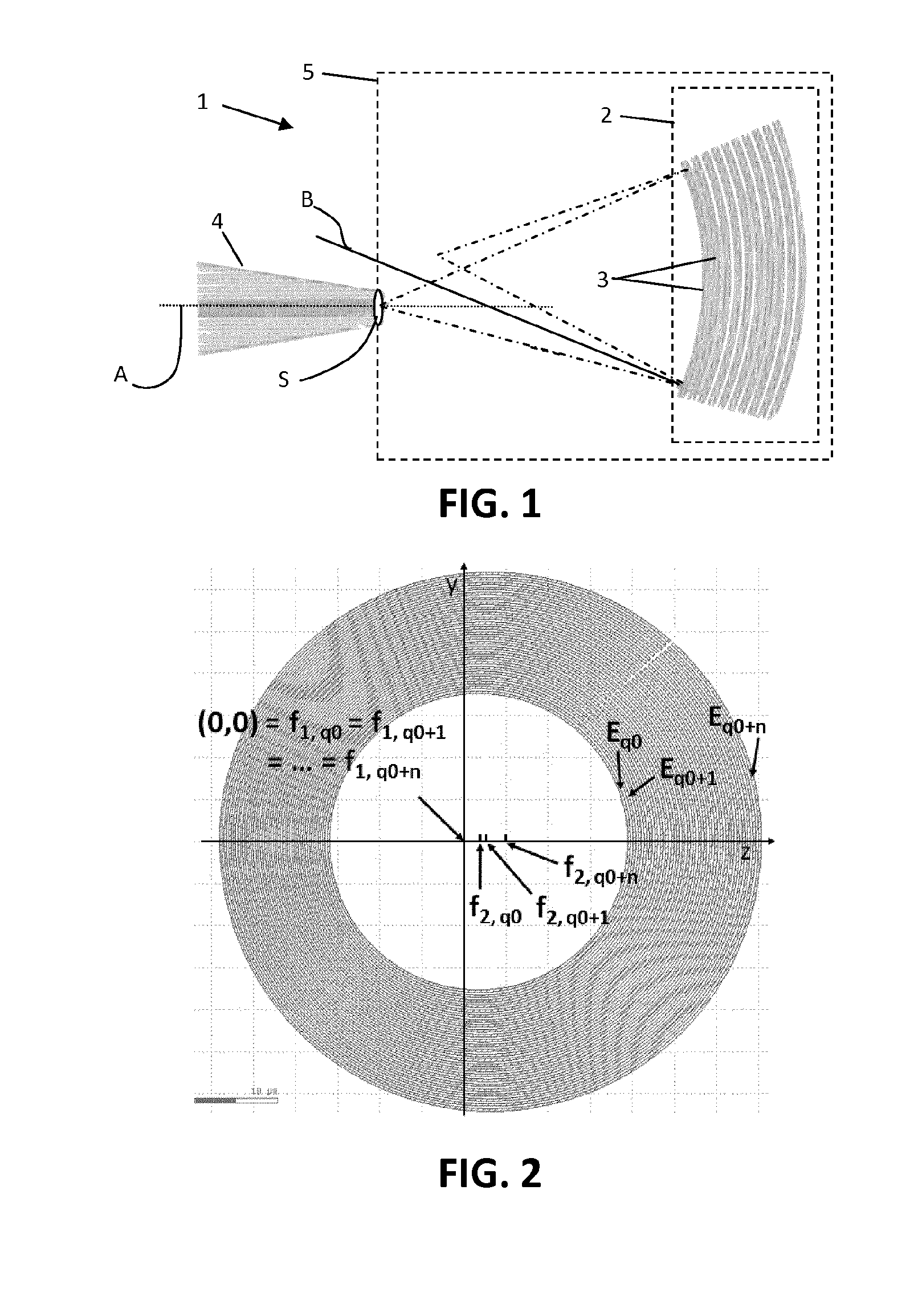
[0020]The grating may be an elliptical grating. It is an advantage of embodiments according to the present invention that a grating can be used having a conventional shape, e.g. an elliptical shape.

Problems solved by technology

Although the high refractive index contrast of SOI reduces the footprint of integrated photonic devices considerably, it becomes more difficult to achieve a high-performance mode-size convertor between a single-mode optical fiber, with a typical cross-sectional area of 100 μm2, and an on-chip integrated optical waveguide, with a typical cross-sectional area in the order of 0.1 μm2.
These levels of back-reflection may be unacceptable for integrated circuits, especially for example for circuits which contain integrated lasers, or which implement interferometer-based designs.
This reflection may be highly dependent on the grating structure itself and may therefore be very difficult to eliminate.

Method used


Image

  • Integrated Photonics Waveguide Grating Coupler
  • Integrated Photonics Waveguide Grating Coupler
  • Integrated Photonics Waveguide Grating Coupler

Examples


Embodiment Construction

[0056]The present invention will be described with respect to particular embodiments and with reference to certain drawings but the invention is not limited thereto but only by the claims. The drawings described are only schematic and are non-limiting. In the drawings, the size of some of the elements may be exaggerated and not drawn on scale for illustrative purposes. The dimensions and the relative dimensions do not correspond to actual reductions to practice of the invention.

[0057]Furthermore, the terms first, second and the like in the description and in the claims, are used for distinguishing between similar elements and not necessarily for describing a sequence, either temporally, spatially, in ranking or in any other manner. It is to be understood that the terms so used are interchangeable under appropriate circumstances and that the embodiments of the invention described herein are capable of operation in other sequences than described or illustrated herein.

[0058]Moreover, t...


PUM


Abstract

A photonic integrated device comprises a waveguide embedded in a photonic substrate. The waveguide has a waveguide radiation exit surface and the waveguide is optically connected to a two dimensional grating. The photonic integrated device also comprises a two dimensional grating having a plurality of curved elongate scattering elements. The two dimensional grating is adapted for diffracting radiation received from the waveguide toward a direction out of the photonic substrate and the curved elongate scattering elements are oriented with respect to the waveguide such that, for points of the scattering elements which can be irradiated by radiations stemming from the waveguide, normal lines to at least the curved elongate scattering element closest to the waveguide radiation exit surface do not substantially intersect with the waveguide radiation exit surface of the waveguide.

Description

FIELD OF THE INVENTION[0001]The invention relates to the field of integrated photonics. More particularly it relates to methods and systems for coupling radiation from an integrated photonics waveguide device to a fiber or to free space or vice versa.BACKGROUND OF THE INVENTION[0002]Photonic integration is considered to be a key technology for future advancement in optical communication technology. Scaling down of the optical building blocks enables cost-effective, complex and ultra-compact photonic circuits, i.e. chips which comprise integrated optical components formed on or in a substrate and which are interconnected by planar waveguides. It is typically desirable to be able to optically couple the signals conducted by such planar waveguides into or out of the integrated chip, for example from or into an optical fiber.[0003]Choosing an appropriate platform for developing this miniaturization technology is guided by functionality, compatibility, performance, yield and cost. Curren...

Claims


Application Information

Patent Timeline
Patent Type & Authority Applications(United States)
IPC IPC(8): G02B6/12G02B6/34G02B6/122
CPCG02B6/12004G02B6/34G02B6/1225G02B6/124G02B6/30G02B6/29316G02B6/29326G02B6/29328
Inventor BAETS, ROELANDVERMEULEN, DIEDRIKLI, YANLUDE KONINCK, YANNICK
Owner UNIV GENT
Why Eureka
Try Eureka