
Contra-rotating propulsor for marine propulsion

a propulsor and contra-rotating technology, applied in the direction of special-purpose vessels, vessel parts, gearing, etc., can solve the problems of higher system acquisition cost, less efficient operation outside, and further complicated

Active Publication Date: 2014-12-11
MICHIGAN MARINE PROPULSION SYST
View PDF5 Cites 18 Cited by
  • Summary
  • Abstract
  • Description
  • Claims
  • Application Information

AI Technical Summary

Benefits of technology

The invention offers a system that uses fixed pitch contra-rotating propulsors to improve efficiency over the entire operating range of the prime mover. It also allows for energy recovery and flexible "hybrid" configurations, resulting in improved efficiency and reduced fuel consumption. Additionally, the invention includes outer fixed field windings that can transfer power from one to another and allow for direct electrical input or output.

Problems solved by technology

Some of the primary challenges in designing a ship propulsion system include the matching of the propulsor elements (propellers or waterjet impellers) to the characteristics of the hull form, mission requirements, and the characteristics and limitations of the prime movers (e.g. diesel engines, gas turbines, electric motors).
This is further complicated by the need to “balance” the performance of the system over the operating range of the prime mover.
The former is a common attempt at solving this problem but the trade-offs are: higher system acquisition cost; propeller blade shape that is optimized for top speed or Bollard Pull characteristics but is less efficient when operating outside this range; and larger propeller propulsor hub size with corresponding reduced overall efficiency.
The use of electric drives has the trade-off of being significantly higher in acquisition cost and has a lower operating efficiency over the entire operating range as a result of the mechanical-to-electrical power conversion.
An additional and more substantial challenge has been identified in Naval Ship applications.
Prior art in the form of conventional single-impeller waterjets has been significantly challenged to “get the horsepower into the water” without causing destructive cavitation and without exceeding the space available on the transom of a narrow, high speed hullform.
Prior attempts to address this challenge using planetary gears with free rotation of planet carriers and ring gears to produce a contra-rotating propulsor fall short in their ability to maximize the efficiency of the system.

Method used


Image

  • Contra-rotating propulsor for marine propulsion
  • Contra-rotating propulsor for marine propulsion
  • Contra-rotating propulsor for marine propulsion

Examples


Embodiment Construction

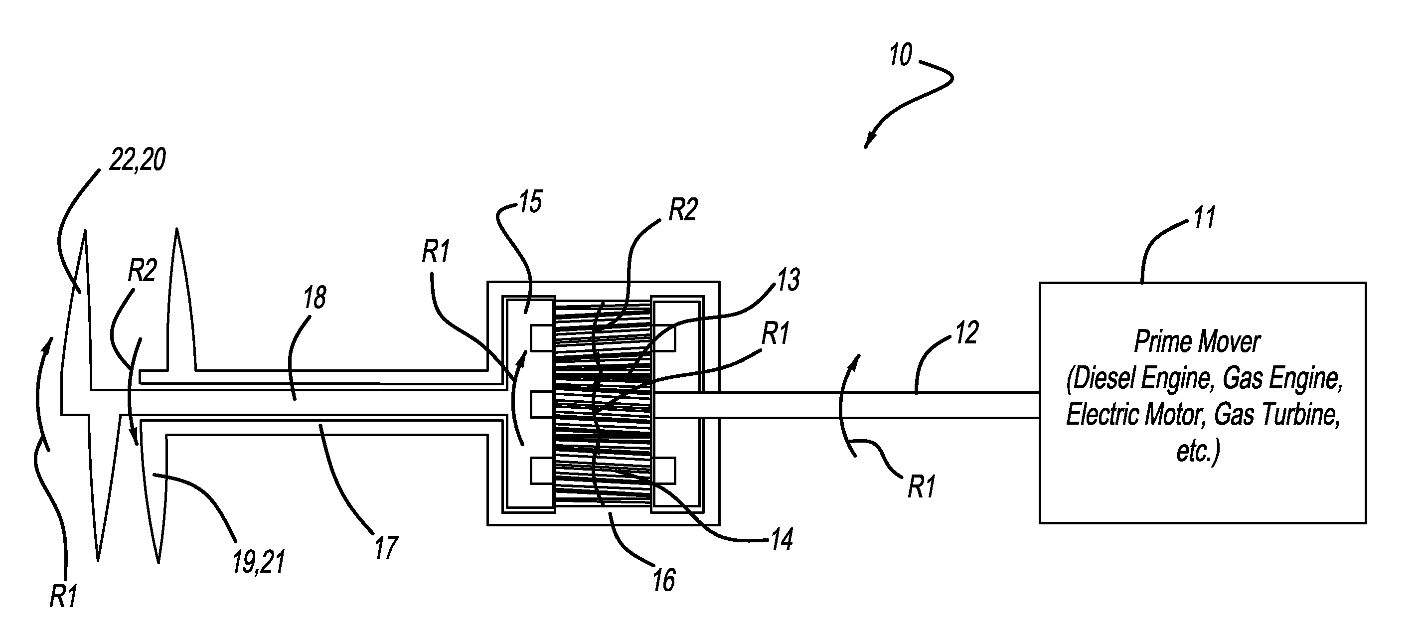
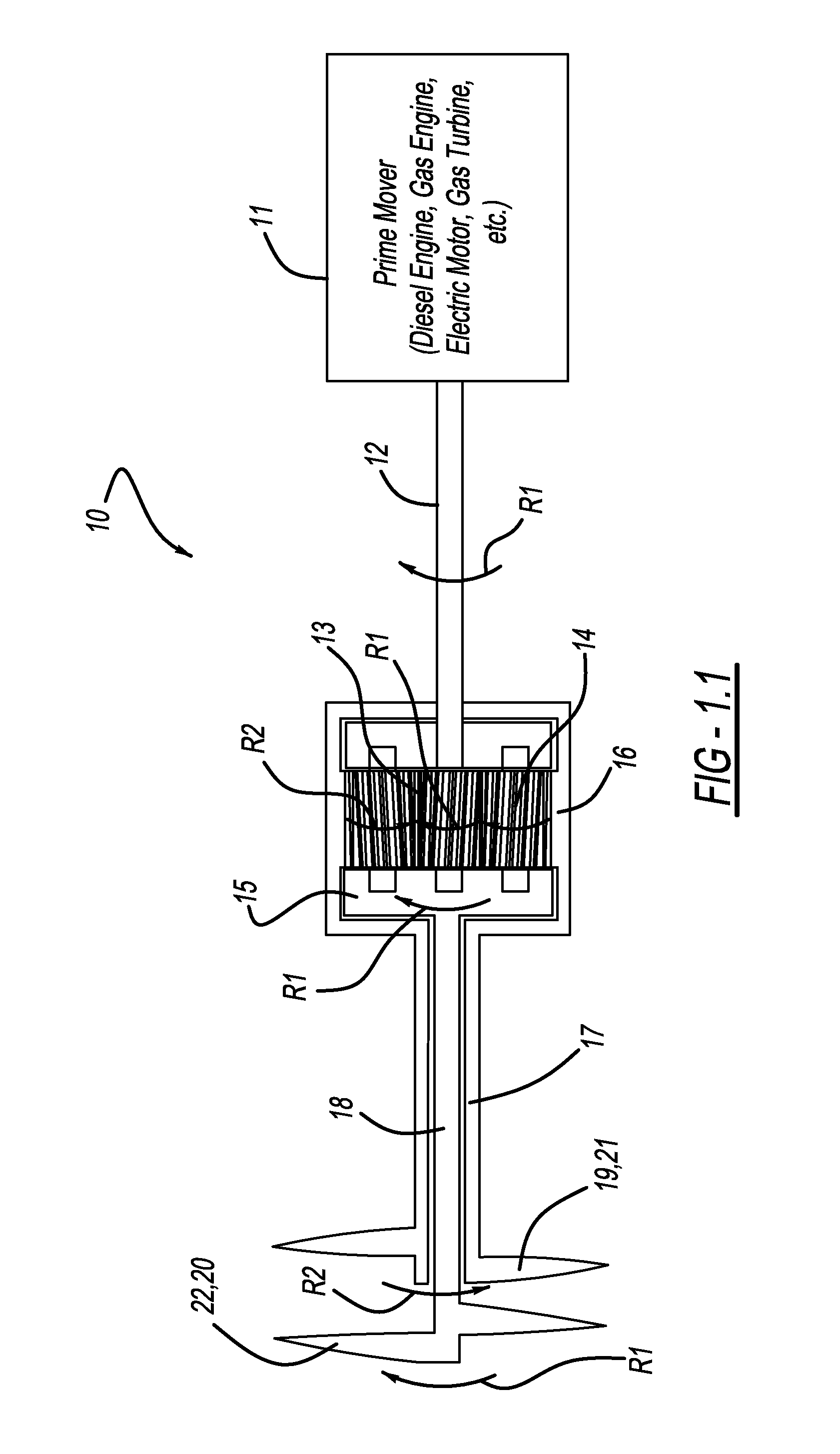
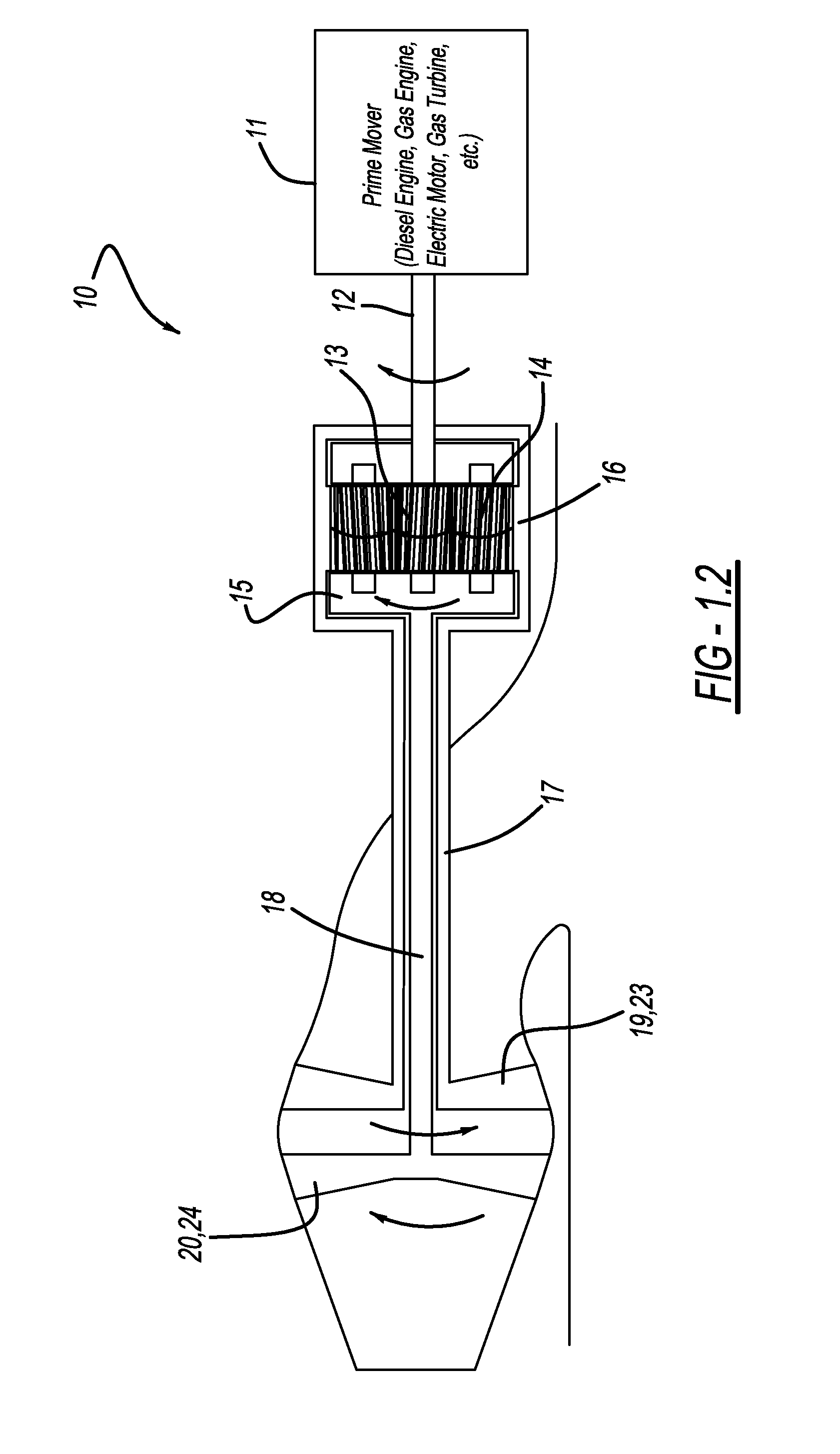
[0032]With reference to FIGS. 1.1 to 4.3, a contra-rotating propulsor system 10 is provided having various embodiments described herein. With reference to FIG. 1.1, the system 10 includes a main power source or prime mover 11 that is configured and arranged to drive an input shaft 12 in a first rotary direction R1. The prime mover 11 and input shaft 12 drives the system through the use of a pinion gear 13, a plurality of planet gears 14, a planet carrier 15, and a ring gear 16. More specifically, the pinion gear 13 is coupled to an end of the input shaft 12 and is directly driven by the input shaft 12 such that the pinion gear rotates in the same rotary direction R1 as the input shaft 12.

[0033]The planet gears 14 are arranged circumferentially around and mesh with the pinion gear 13 and are each coupled to the planet carrier 15. The planet gears 14 can each rotate about their individual axes relative to the planet carrier 15. The planet carrier 15 holds the planet gears 14 in their ...


PUM


Abstract

A system for providing marine propulsion is provided including an input shaft driven by a prime mover, a pinion gear coupled to the input shaft, a plurality of planet gears coupled to the pinion gear, a planet carrier having the plurality of planet gears rotationally mounted thereto, and a ring gear surrounding the planet gears and coupled thereto. The planet carrier and ring gear are coupled to internal and external output shafts that are coaxially aligned, which are coupled to aft and forward propulsor elements. The ring gear and planet carrier rotate in opposite directions to provide contra-rotating forward and aft propulsor elements. The ring gear and planet gear are each coupled to rotation altering devices that, when at least one is activated, the rotation of both the planet carrier and ring gear will be altered, thereby altering the rotation of the propulsor elements.

Description

CROSS-REFERENCE TO RELATED APPLICATIONS[0001]This application claims the benefit of U.S. Provisional Patent Application No. 61 / 789,176, filed Mar. 15, 2013, which is hereby incorporated by reference in its entirety.BACKGROUND[0002]Marine or ship propulsion has been achieved in a variety of ways over time, including the use of propulsor elements such as propellers or waterjet impellers. Some of the primary challenges in designing a ship propulsion system include the matching of the propulsor elements (propellers or waterjet impellers) to the characteristics of the hull form, mission requirements, and the characteristics and limitations of the prime movers (e.g. diesel engines, gas turbines, electric motors). This is further complicated by the need to “balance” the performance of the system over the operating range of the prime mover.[0003]Historically, ship propulsion systems have been optimized to address a key performance point for the application. For example, Ship Assist Tugs are...

Claims


Application Information

Patent Timeline
Patent Type & Authority Applications(United States)
IPC IPC(8): B63H23/06B63H23/30F16H1/46
CPCB63H23/06B63H2023/062B63H23/30F16H1/46B63H5/10B63H11/00B63H23/24B63H23/28B63H2005/106B63H2021/202B63H2023/0283B63H2023/065B63H2023/067B63H2023/245B63B34/05Y02T70/50Y02T70/5236B63H23/02
Inventor BENTGEN, BERNARDSAVANDER, BRANT
Owner MICHIGAN MARINE PROPULSION SYST
Learn More