
Adaptation of a power generation capacity and determining of an energy storage unit size

a technology of power generation capacity and energy storage unit, applied in the direction of load forecasting in ac network, pulse technique, instruments, etc., can solve the problems of increasing the cost of both above methods, the cost of adjusting the power generation capacity, etc., to achieve the effect of decreasing the capacity

Inactive Publication Date: 2014-12-11
THOMSON LICENSING SA
View PDF8 Cites 40 Cited by
  • Summary
  • Abstract
  • Description
  • Claims
  • Application Information

AI Technical Summary

Benefits of technology

The patent describes a method for adjusting the power generation capacity of a power grid to meet varying demand. The method involves measuring the load unit demand in real-time, and adjusting the power generation capacity accordingly to ensure that the demand is met while minimizing the likelihood of power outages. This allows for quick and flexible adjustments to the power generation capacity, improving the reliability of the power grid.

Problems solved by technology

Both above methods are costly.
Spinning reserve plants running below maximum output usually produce at less than their best efficiency and the expensive generating equipment at the additional power plants remain unused much of the time.
They are not designed to handle real-time stochastic energy sources and demands that arise from grid-connected intermittent energy sources such as solar cells and wind turbines.
Despite the high potential and increased usage of energy storage in electric power grids, it is not yet clear how to design and operate such a system in an efficient manner.
This yields a conservative design when the peak load of the worst duty cycle is much higher than the average and cannot be applied to the case of stochastic energy sources and / or demands.

Method used


Image

  • Adaptation of a power generation capacity and determining of an energy storage unit size
  • Adaptation of a power generation capacity and determining of an energy storage unit size
  • Adaptation of a power generation capacity and determining of an energy storage unit size

Examples


Embodiment Construction

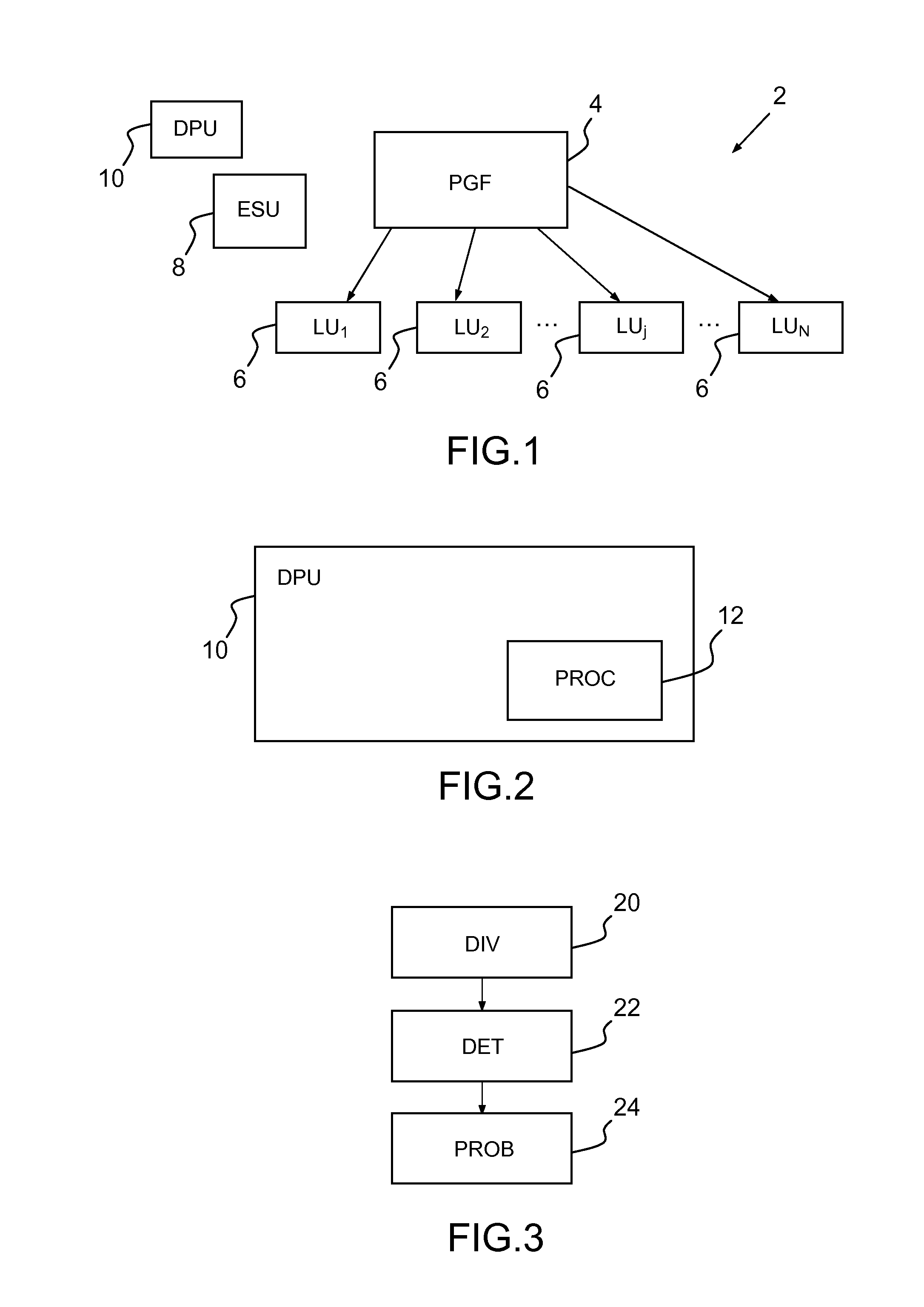
[0056]Following, the invention will be described in further detail, by way of examples, and not by way of limitation, in the figures of the accompanying drawings, in which like reference numerals refer to similar elements and in which:

[0057]FIG. 1 is a schematic view of an electrical power grid according to an embodiment of the present invention;

[0058]FIG. 2 is a schematic view of a data processing unit according to an embodiment of the present invention; and

[0059]FIG. 3 is a flowchart illustrating the steps of the method for determining a power outage probability according to an embodiment of the present invention.

[0060]An electrical power grid 2, in particular a smart grid, is considered where a power generation facility PGF 4 distributes power to several load units LUs 6, such as homes or industrial facilities, using a battery which serves as an energy storage unit ESU 8. The LUs 6 create electricity demands that must be matched by the PGF 4. When the aggregate demand of the LUs ...


PUM


Abstract

A method for determining a power outage probability of an electrical power grid for a time period, the method comprising the following steps carried by a processor of a data processing unit:dividing the time period into several time intervals,determining a power generation capacity of a power generation facility and an energy storage unit size for an energy storage unit for said time period,determining an effective load unit demand for each time interval from a load unit demand of a load unit for each time interval, andcomputing the power outage probability using a grid parameter that comprises the power generation capacity, the energy storage unit size and the effective load unit demand, wherein the grid parameter is optimized for its maximum value with respect to all time intervals of the time period

Description

[0001]The invention relates to a method for determining a power outage probability of an electrical power grid, a method for an adaptation of a power generation capacity and a method for determining an energy storage unit size. It also relates to a data processing unit.BACKGROUND OF THE INVENTION[0002]Electrical power grid systems usually combine power generated by fuel-based power plants (i.e. coal, oil, gas) with variable energy sources from wind, solar and micro-hydel. Fuel-based power plants must be scaled up and down to match the rise and fall of energy production from the variable energy sources and varying demands.[0003]Two basic methods are used to deal with changing demands. First, the fuel-based power plants can be run below their maximum output and then quickly increase the amount of generated power when needed (spinning reserve). Second, additional power plants (e.g. based on combustion gas turbines) can be brought up (in a matter of minutes) to provide a larger generati...

Claims


Application Information

Patent Timeline
Patent Type & Authority Applications(United States)
IPC IPC(8): G06N7/00H02J4/00
CPCH02J4/00G06N7/00G06Q10/04G06Q50/06Y02P90/82H02J3/003H02J2203/20Y02E60/00Y04S40/20Y04S10/50Y04S20/222Y02B70/3225H02J3/0012H02J3/00
Inventor SALONIDIS, THEODOROSMASSOULIE, LAURENTKESHAV, SRINIVASSANHEGDE, NIDHI
Owner THOMSON LICENSING SA
Learn More