Continuous ignition

a technology of continuous ignition and ignition system, which is applied in the ignition of burners, ignition devices of turbine/propulsion engines, lighting and heating apparatuses, etc., can solve the problems of increasing the difficulty of ignition, reducing the flame strength of the ignition device, so as to achieve the effect of increasing the flame strength and decreasing the flame strength

Active Publication Date: 2014-12-18
COLLINS ENGINE NOZZLES INC
View PDF13 Cites 43 Cited by
  • Summary
  • Abstract
  • Description
  • Claims
  • Application Information

AI Technical Summary

Benefits of technology

[0012]Also disclosed is a new and useful method of combustion stabilization for a combustor in a gas turbine engine. The method includes detecting a combustion instability in a combustor and issuing a flame from the exhaust outlet of an ignition system as described above into the combustor to stabilize combu...

Problems solved by technology

This increased concentration of fuel can wet the igniter, making it more difficult to light and can lead to carbon formations which will also make ignition more difficult.
Typical igniters can fail instantaneously and without warning, which also requires special design considerations in anticipation of failure.
The high voltages that are used to generate the spark can often find alternate paths in the circuit leading to the spark surface across which they can discharge and in such cases, the igniters can fail to provide an adequate spark for engine ignit...

Method used


Image

  • Continuous ignition
  • Continuous ignition
  • Continuous ignition

Examples


Embodiment Construction

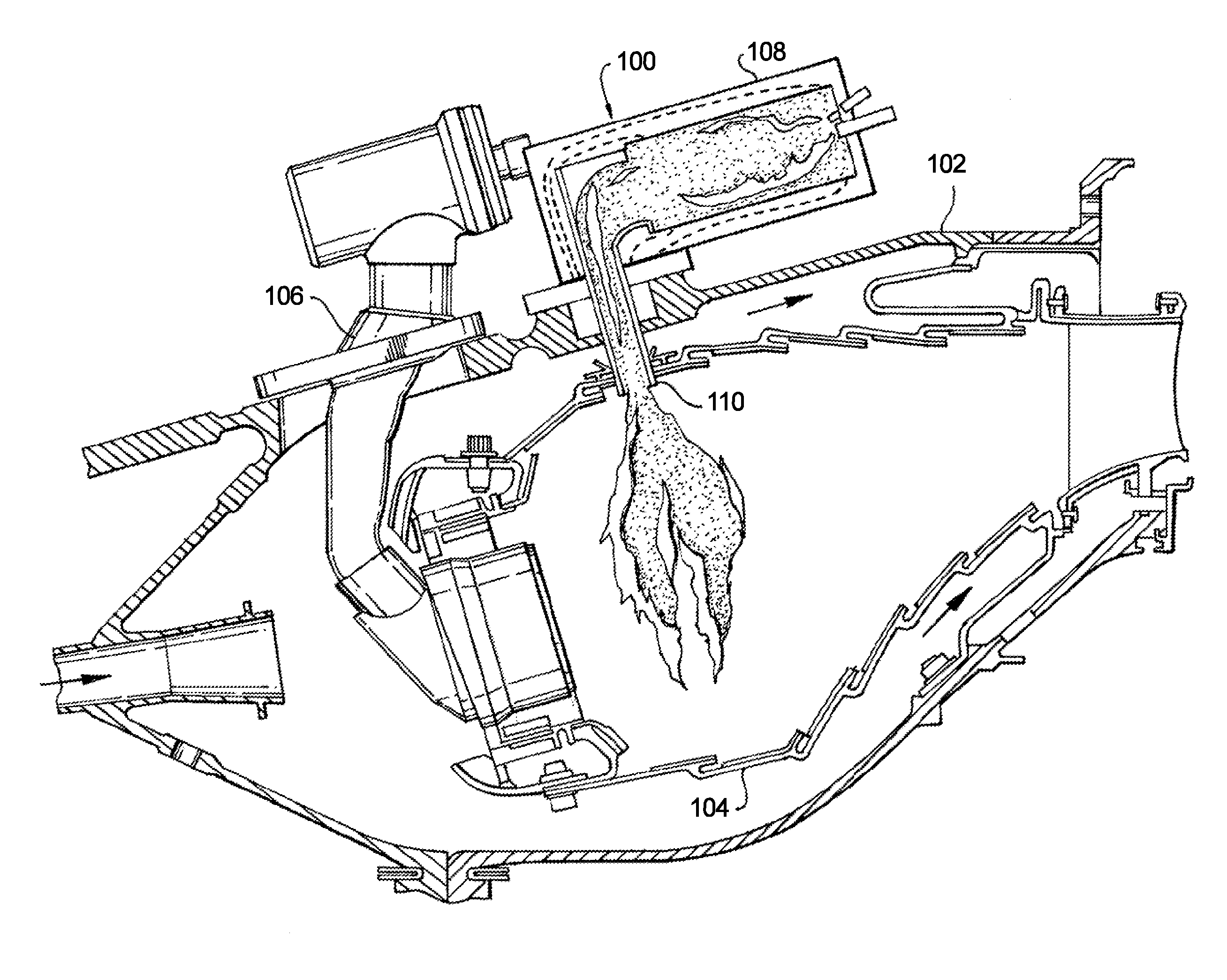
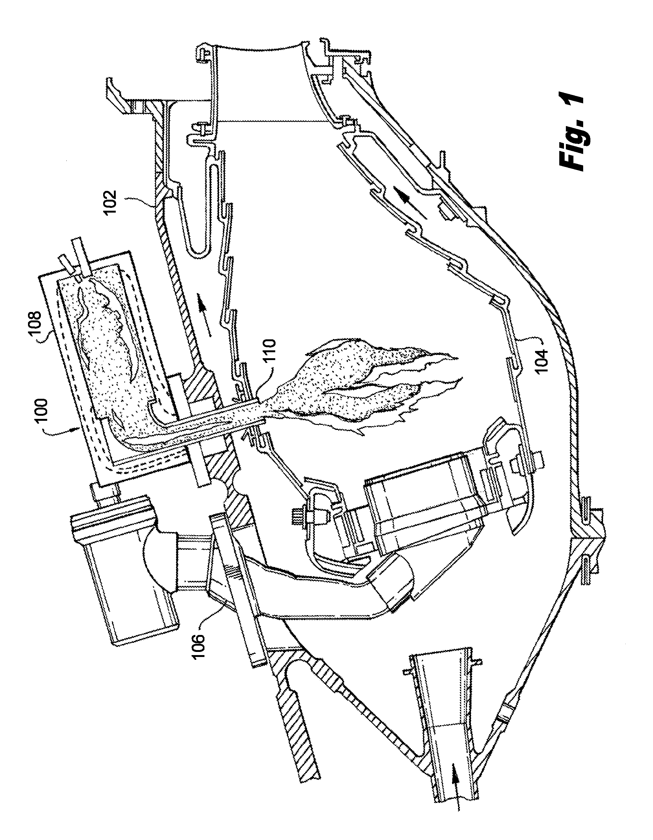
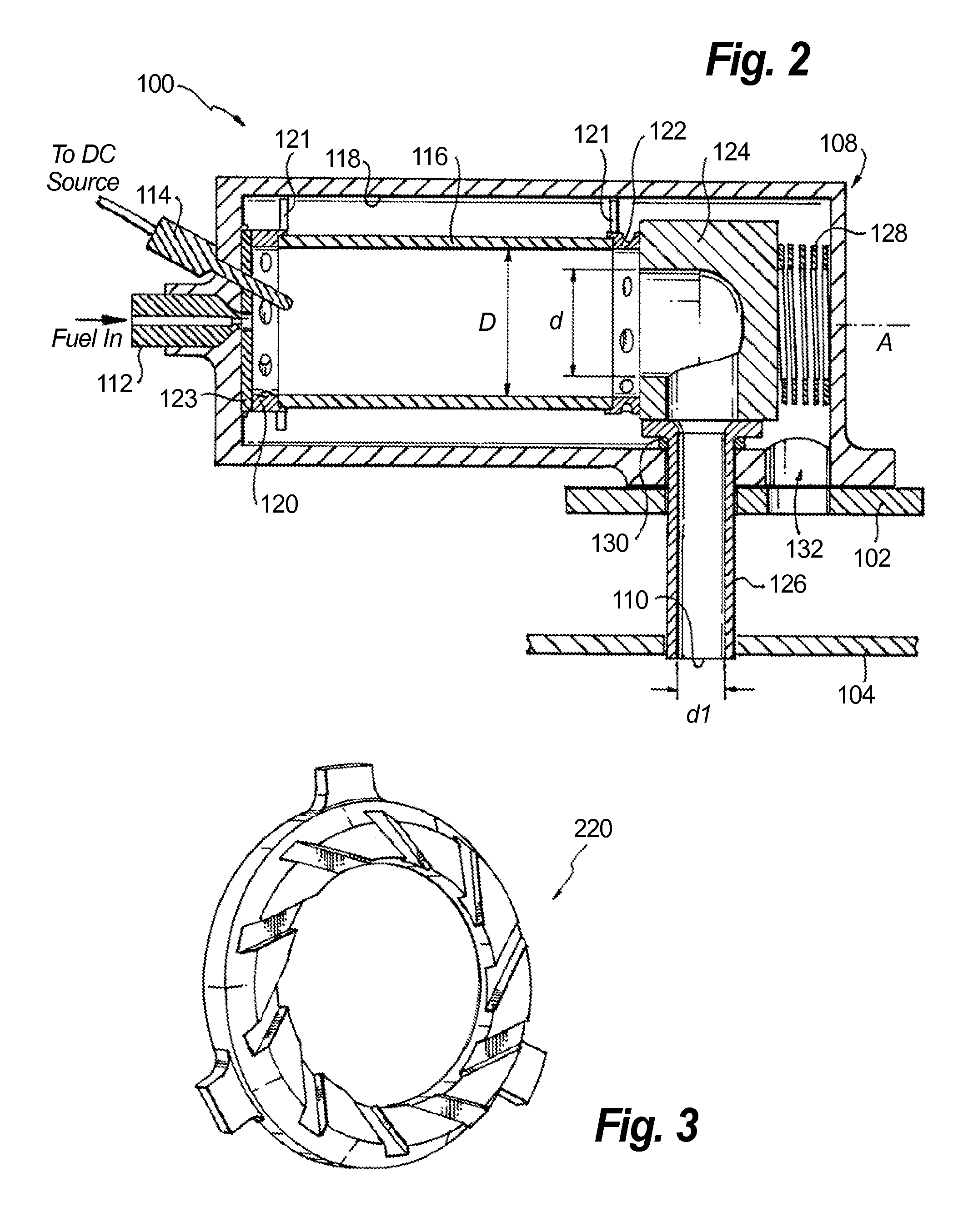
[0022]Reference will now be made to the drawings wherein like reference numerals identify similar structural features or aspects of the subject invention. For purposes of explanation and illustration, and not limitation, a partial view of an exemplary embodiment of an ignition system is shown in FIG. 1 and is designated generally by reference character 100. Other embodiments of ignition systems, or aspects thereof, are provided in FIGS. 2-7, as will be described. The systems and methods of the invention can be used, for example, to employ liquid fuel injection to improve the ignition performance of advanced engines. The systems and methods can be used in new engines, as well as to retrofit to existing engines to replace traditional ignition systems, for example.

[0023]In FIG. 1, ignition system 100 is shown mounted to a high pressure casing 102 outboard of a combustor 104 of a gas turbine engine. Compressor discharge air enters the high pressure casing on the right hand side of FIG. ...


PUM


Abstract

An ignition system includes a housing defining an interior and an exhaust outlet. The housing is configured and adapted to be mounted to a combustor to issue flame from the exhaust outlet into the combustor for ignition and flame stabilization within the combustor. A fuel injector is mounted to the housing with an outlet of the fuel injector directed to issue a spray of fuel into the interior of the housing. An igniter is mounted to the housing with an ignition point of the igniter proximate the outlet of the fuel injector for ignition within the interior of the housing.

Description

BACKGROUND OF THE INVENTION[0001]1. Field of the Invention[0002]The present invention relates to combustion, and more particularly to ignition systems such as in gas turbine engines.[0003]2. Description of Related Art[0004]A variety of devices are known for initiating combustion, for example in a gas turbine engine. Many gas turbine engines use spark igniters for ignition. One or more spark igniters are positioned to ignite a fuel and air mixture to initiate the flame in the combustor. These typical igniters provide ignition energy intermittently, and the spark event must coincide with a flammable mixture local to the igniter in order for engine ignition to occur. Often this means fuel will be sprayed toward the combustor wall near the igniter to improve the chances of ignition. This increased concentration of fuel can wet the igniter, making it more difficult to light and can lead to carbon formations which will also make ignition more difficult. Although the igniter is used for a ...

Claims


Application Information

Patent Timeline
IPC IPC(8): F23R3/20F23R3/14
CPCF23R3/14F23R3/20F23R3/28F23C2900/03005F23D2207/00F23D2900/11401F23N2227/02
Inventor PROCIW, LEV ALEXANDERRYON, JASON ALLENMYERS, STEVEN JAYNELSON, NICOLE L.SEEI, ROGER A.
Owner COLLINS ENGINE NOZZLES INC
Why Eureka
Try Eureka