Unlock instant, AI-driven research and patent intelligence for your innovation.

Multi charged particle beam writing method, and multi charged particle beam writing apparatus

Active Publication Date: 2014-12-18
NUFLARE TECH INC
View PDF9 Cites 7 Cited by
  • Summary
  • Abstract
  • Description
  • Claims
  • Application Information

AI Technical Summary

Benefits of technology

The present invention provides a multi charged particle beam writing method and apparatus for use in multi-pass writing. The method involves converting a first gray scale value into a binary number of a predetermined digit number set in advance, by dividing the total irradiation time of all the beams into a set of irradiation steps. The method also involves irradiating the target object with multiple beams each having a predetermined irradiation time, using a set of irradiation steps as a set of irradiation steps for each writing processing of the multi-pass writing. The apparatus includes a stage for mounting the target object, an emission unit for emitting the charged particle beam, an aperture member for forming multiple beams, blankers for deflecting the beams, and a conversion unit for converting the first gray scale value into a binary number. The technical effects of the invention include improved accuracy and efficiency in multi-pass writing, reduced irradiation time, and improved precision in target object positioning.

Problems solved by technology

However, since the space for placing a circuit on a blanking plate and the amount of current to be used are restricted, there is no other alternative but to have an uncomplicated circuit for the amount of information of control signals.
Therefore, it has been difficult to build in a blanking circuit that can perform an operation of high speed and high precision.
Further, installing a blanking control circuit for each beam on a blanking plate restricts to narrow the pitch of multiple beams.
By contrast, when placing a control circuit for each beam outside the writing apparatus body and connecting each of them by wiring in order to secure a space for installing the circuit, since the wiring becomes long, there is a problem that a crosstalk problem becomes more prominent.

Method used


Image

  • Multi charged particle beam writing method, and multi charged particle beam writing apparatus
  • Multi charged particle beam writing method, and multi charged particle beam writing apparatus
  • Multi charged particle beam writing method, and multi charged particle beam writing apparatus

Examples


first embodiment

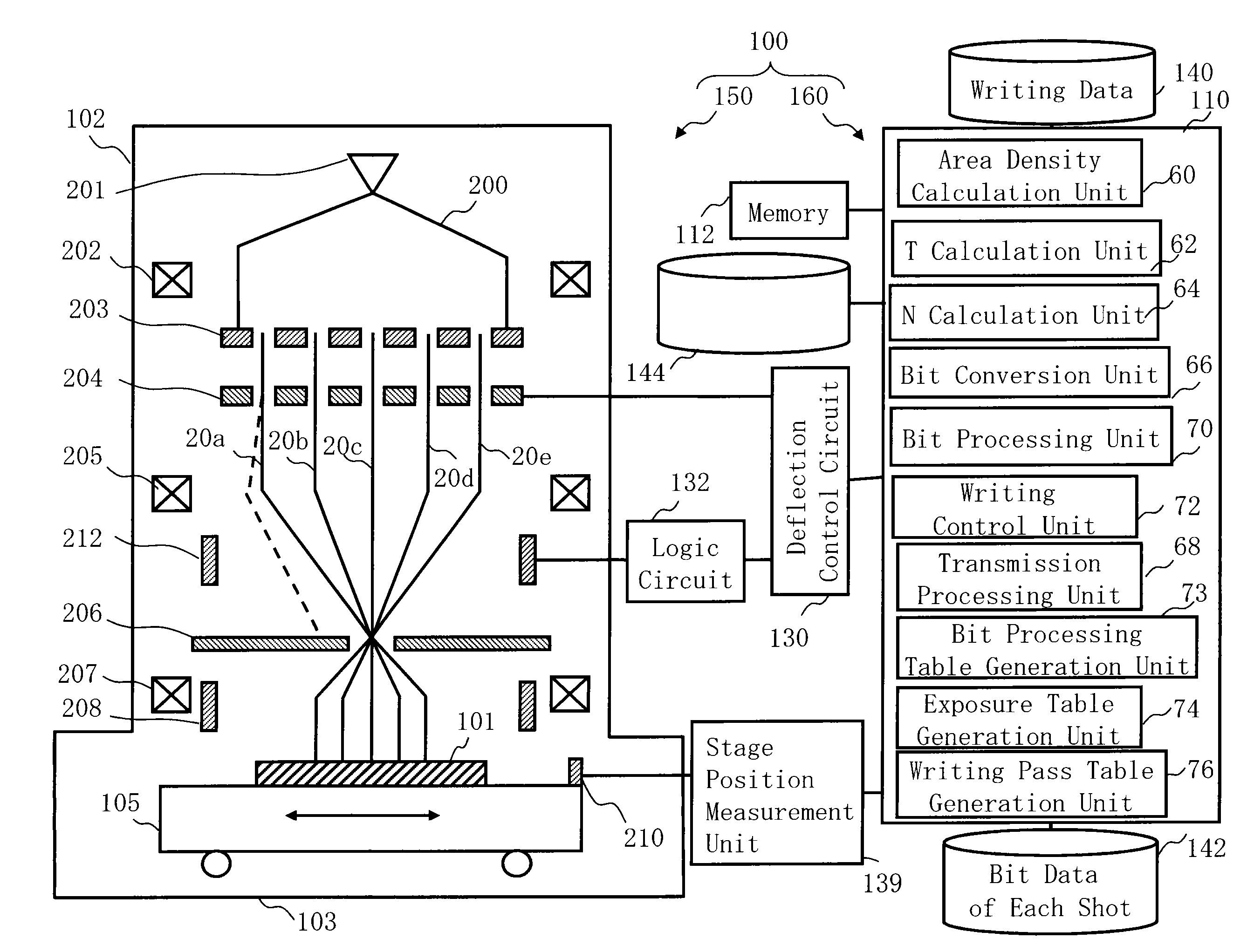
[0045]FIG. 1 is a schematic diagram showing a configuration of a writing apparatus according to the first embodiment. In FIG. 1, a writing (or “drawing”) apparatus 100 includes a writing unit 150 and a control unit 160. The writing apparatus 100 is an example of a multi charged particle beam writing apparatus. The writing unit 150 includes an electron optical column 102 and a writing chamber 103. In the electron optical column 102, there are arranged an electron gun assembly 201, an illumination lens 202, an aperture member 203, a blanking plate 204, a reducing lens 205, a deflector 212, a limiting aperture member 206, an objective lens 207, and a deflector 208. In the writing chamber 103, there is arranged an XY stage 105. On the XY stage 105, there is placed a target object or “sample”101 such as a mask serving as a writing target substrate when performing writing. The target object 101 is, for example, an exposure mask used for manufacturing semiconductor devices, or a semiconduc...

second embodiment

[0122]In the first embodiment, the case where writing processing is repeatedly performed without shifting the position in each writing pass of multi-pass writing has been described, but however, it is not limited thereto. In the second embodiment, there will be explained the case where multi-pass writing that combines the processing (the first writing processing) of repeatedly performing writing processing while shifting the position of a deflection region, and the processing (the second writing processing) of repeatedly performing writing processing without further shifting the position, at the position in each deflection region having been shifted. The apparatus structure of the writing apparatus 100 is the same as that of FIG. 1. The flowchart showing main steps of the writing method according to the second embodiment is the same as that of FIG. 7. Hereafter, the contents of the second embodiment are the same as those of the first embodiment except what is particularly described ...

third embodiment

[0138]Although, in each embodiment described above, blanking control is performed for each of a plurality of irradiation steps made by dividing shots of all the passes in multi-pass writing where no position shifting is performed, for each beam, by using the blanking plate 204 for individual blanking control and the deflector 212 for common blanking, it is not limited thereto. In the third embodiment, there will be described a configuration in which blanking control is performed for each of a plurality of irradiation steps made by dividing shots of all the passes in multi-pass writing where no position shifting is performed, by using the blanking plate 204 for individual blanking control without using the deflector 212 for common blanking.

[0139]FIG. 26 is a schematic diagram showing the structure of a writing apparatus according to the third embodiment. FIG. 26 is the same as FIG. 1 except that the deflector 212 does not exist and output of the logic circuit 132 is connected to the ...


PUM


Abstract

A multi-beam writing method includes irradiating a target object with a multi-beam each being one of beams of irradiation time periods of a set of irradiation steps corresponding to writing processing concerned of plural writing processing of the multi-pass writing, for each writing processing of the multi-pass writing, using each set of irradiation steps, obtained by dividing entire irradiation steps of all the number of writing times of a beam concerned into a predetermined digit number irradiation steps to be set as an irradiation time obtained by multiplying a corresponding second gray scale by a quantization unit, as a set of irradiation steps of one of the plural writing processing of the multi-pass writing, wherein the corresponding second gray scale is one of plural second gray scales defined in decimals converted from each digit value of a binary number of a predetermined digit number.

Description

CROSS-REFERENCE TO RELATED APPLICATION[0001]This application is based upon and claims the benefit of priority from the prior Japanese Patent Application No. 2013-124437 filed on Jun. 13, 2013 in Japan, the entire contents of which are incorporated herein by reference.BACKGROUND OF THE INVENTION[0002]1. Field of the Invention[0003]The present invention relates to a multi charged particle beam writing method and a multi charged particle beam writing apparatus. More specifically, for example, the present invention relates to a multi-pass writing method in writing with multiple beams.[0004]2. Description of Related Art[0005]The lithography technique that advances miniaturization of semiconductor devices is extremely important as being a unique process whereby patterns are formed in the semiconductor manufacturing. In recent years, with high integration of LSI, the line width (critical dimension) required for semiconductor device circuits is decreasing year by year. The electron beam (EB...

Claims


Application Information

Patent Timeline
IPC IPC(8): H01J37/317H01J37/30
CPCH01J37/3007H01J37/3177H01J37/3026H01J37/304H01J2237/31764H01J2237/3175H01L21/0275H01J37/302
Inventor MATSUMOTO, HIROSHI
Owner NUFLARE TECH INC