
X-ray generation devices and methods

Inactive Publication Date: 2014-12-18
CHIRAL RES
View PDF1 Cites 7 Cited by
  • Summary
  • Abstract
  • Description
  • Claims
  • Application Information

AI Technical Summary

Benefits of technology

This patent is about a new kind of x-ray device that is different from regular x-ray sources. It has many benefits, including low energy requirements, low operating temperature, and affordability. It is portable and easy to reconfigure. It does not use any high voltage, or any other potentially harmful materials. Additionally, it does not require any adhesive tape or peeling of layers to function. The device is mechanical and does not generate x-rays from high-voltage electrical effects. It is also lightweight and not reliant on piezoelectric components. Overall, this new x-ray device is safer, more energy-efficient, and easier to use than traditional x-ray sources.

Problems solved by technology

However, most conventional x-ray sources involve the use of heavy, large tubes which consume large amounts of power and require substantial cooling by water, air, or oil.
The tubes typically only convert less than 10% of the total power applied, leading to a substantial loss of energy.
Radiation energy that is too high will result in poor imaging since the radiation cannot be readily attenuated; radiation energy that is too low will increase the radiation dosage of the patient without improvements in image quality.
Too large a photon source results in more blurring in the final image and is worsened by an increase in image formation distance.

Method used


Image

  • X-ray generation devices and methods
  • X-ray generation devices and methods
  • X-ray generation devices and methods

Examples


Embodiment Construction

[0031]While exemplary embodiments are described herein in sufficient detail to enable those skilled in the art to practice the invention, it should be understood that other embodiments may be realized and that logical structural, material, and mechanical changes may be made without departing from the spirit and scope of the invention. Thus, the following detailed description is presented for purposes of illustration only.

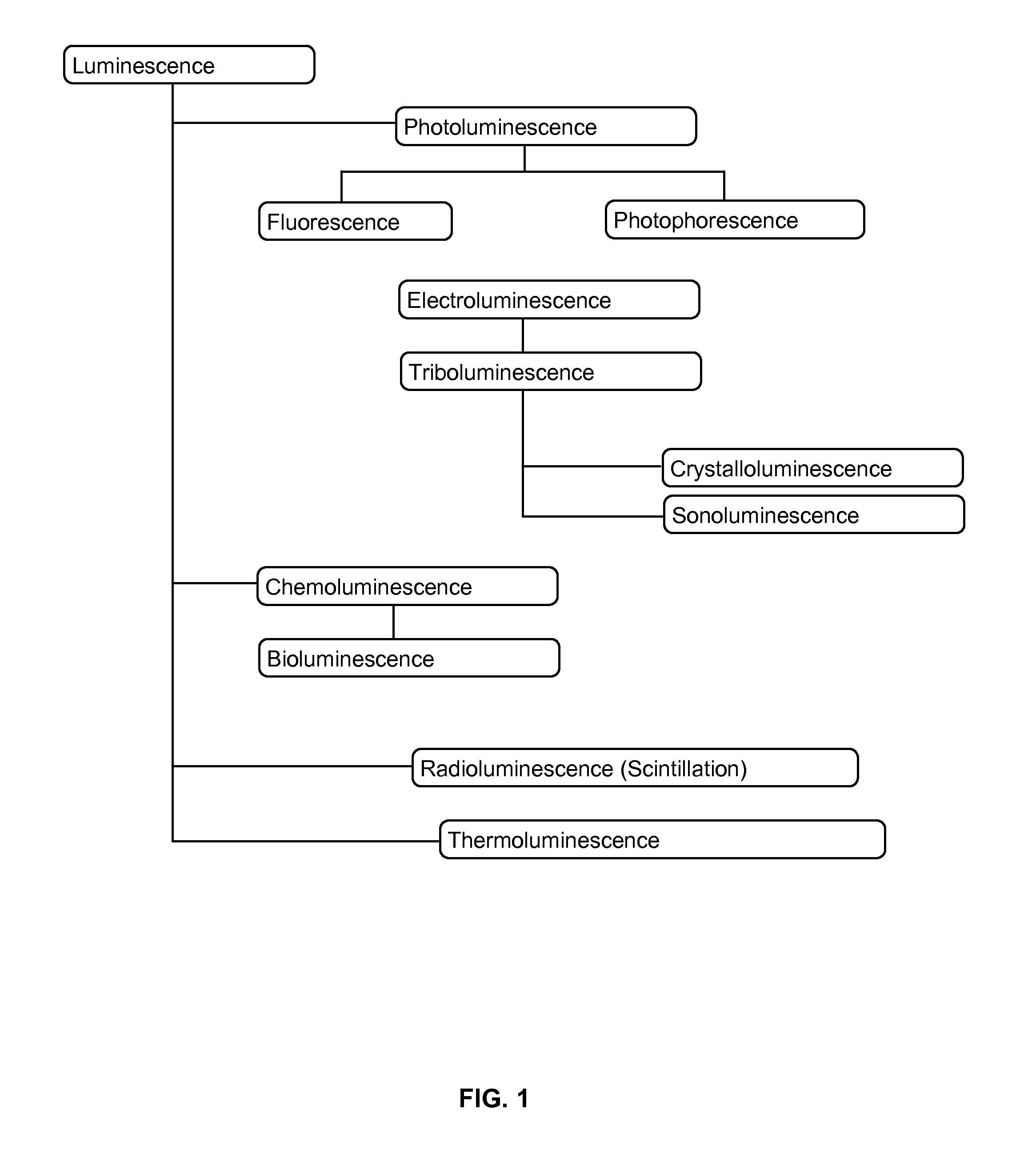
[0032]Electricity comes from the Greek word for amber-electron (ηλ∈κτρον). The Greek prefix ‘tribo’ means rubbing or friction. The triboelectric phenomenon from friction rubbing or impact is seen throughout history and in a variety of fields. The Greeks first characterized this to assist their basic understanding of atoms. “Electroluminescence” is a Luminescence excited in gases and solids by applying an electromagnetic field (see FIG. 1). Molecules are excited upon creation of any form of electric discharge in a material. Electroluminescence of gases is used in dis...


PUM


Abstract

The present disclosure describes an x-ray generating device comprising at least one pair of rotating objects kept in constant frictional contact. In various embodiments, a first rotating object comprises an outer surface material with RDP of ∈1, a second rotating object comprises a second outer surface material with RDP of ∈2, ∈1 does not equal ∈2 and Δ∈ may be maximized by material selection, wherein the rotating objects are positioned in close proximity such that their first and second outer surface materials are kept in constant frictional contact, and wherein x-ray radiation is generated during rotation of the objects.

Description

CROSS REFERENCE TO RELATED APPLICATIONS[0001]This application claims priority to U.S. Provisional Patent Application Ser. No. 61 / 834,380 filed Jun. 12, 2013, and to U.S. Provisional Patent Application Ser. No. 61 / 992,059 filed May 12, 2014, the entire contents of which are incorporated herein by reference.FIELD OF THE INVENTION[0002]The present disclosure relates generally to radiation sources and in particular to a mechanical x-ray generating device.BACKGROUND OF THE INVENTION[0003]X-rays have been known and used since the days of Roentgen in 1900. However, most conventional x-ray sources involve the use of heavy, large tubes which consume large amounts of power and require substantial cooling by water, air, or oil. The tubes typically only convert less than 10% of the total power applied, leading to a substantial loss of energy.[0004]Conventional x-ray photons are generated in events involving electrons and are one form of ionizing electromagnetic radiation used in medical radiogr...

Claims


Application Information

Patent Timeline
IPC IPC(8): H05G2/00
CPCH05G2/00
Inventor NOTTKE, FRANCIS ANTHONYSELIGMANN, RANDOLPH EDWARD
Owner CHIRAL RES
Learn More