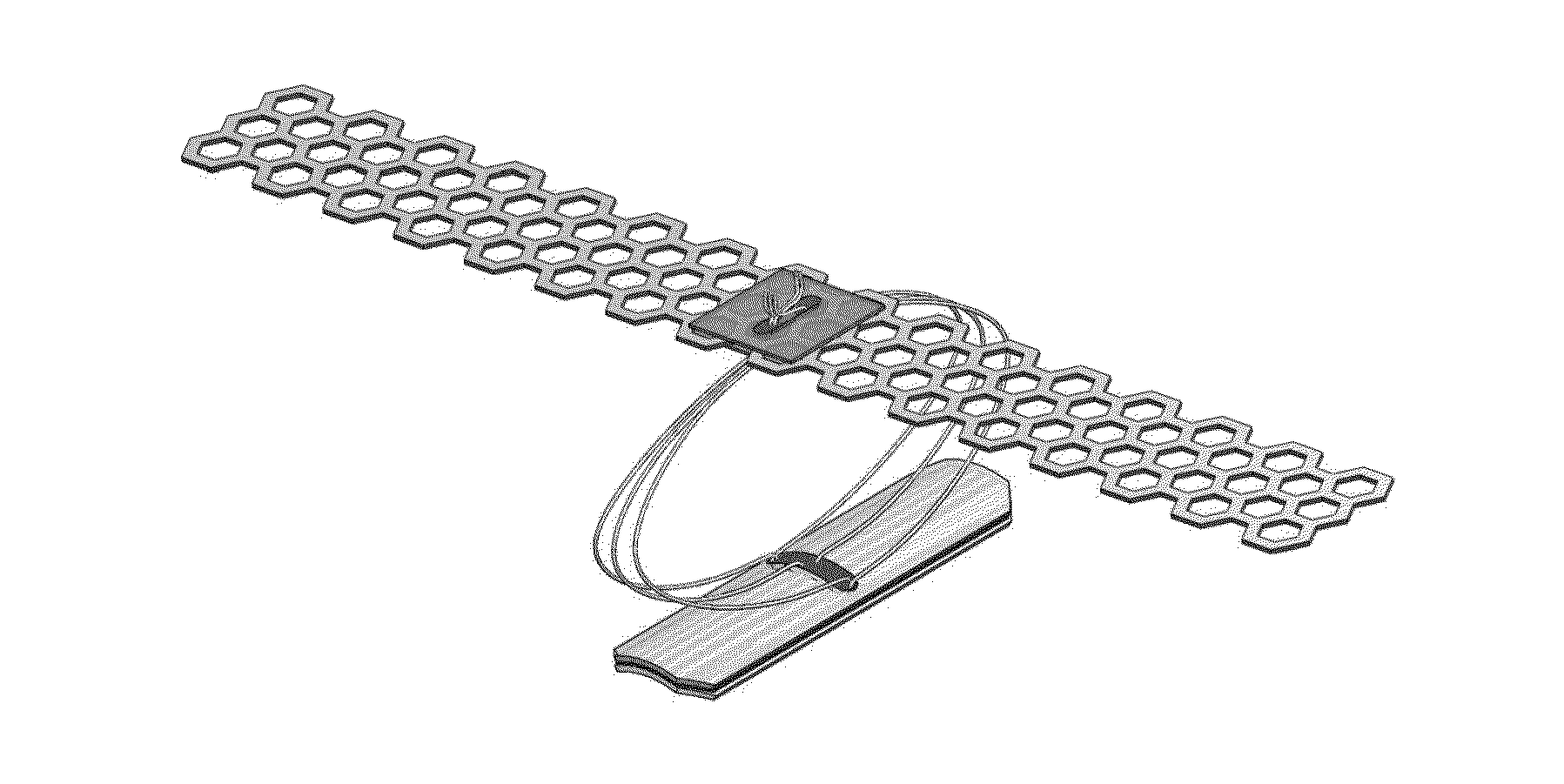
System that secures an electrode array to the spinal cord for treating back pain

a technology of electrode arrays and spinal cords, applied in the field of medical devices and pain management, can solve the problems of affecting the basic activities of patients, affecting the quality of life of patients,

Active Publication Date: 2014-12-18
UNIV OF IOWA RES FOUND
View PDF1 Cites 11 Cited by
  • Summary
  • Abstract
  • Description
  • Claims
  • Application Information

AI Technical Summary

Benefits of technology

[0013]The electrodes can be arrayed on a compliant backing that further comprises semi-rigid extensions in rostral and/or caudal directions and/or lateral directions that increase surface area of the backing in contact with the spinal cord. Thus, the electrodes are disposed on a flexible substrate configured to conform to the spinal cord, wherein the array has opposed axial ends along the spinal

Problems solved by technology

Chronic pain is an often unbearable sequelae of spinal cord injury or disease.
It can interf

Method used


Image

  • System that secures an electrode array to the spinal cord for treating back pain
  • System that secures an electrode array to the spinal cord for treating back pain
  • System that secures an electrode array to the spinal cord for treating back pain

Examples


example 1

Optimization of the Electrode Array Structure Using Thoracic Spine Imaging Data

[0112]An important dimensional parameter for a spinal cord stimulator array is the arc length that it subtends over the dorsal surface of the spinal cord. There are conflicting design goals. One is to make that span as long as possible, in order to maximize the number of electrodes and hence the stimulus-pattern coverage of the underlying dorsal columns. However, another is to ensure that the membrane does not make mechanical contact with the dorsal rootlets.

[0113]In this study, structural dimensions of the spinal cord at the level of the 4th through 10th thoracic vertebrae were investigated (the region in which the array would be placed when treating back and leg pain). The arc length “S” between dorsal-root entry zones (DREZ) was calculated in two ways from magnetic resonance (MR) images of the thoracic spine for 50 patients seen at the University of Iowa Hospitals and Clinics.

[0114]One axial and sagitt...

example 2

MR-Based Measurement of Spinal Cord Motion During Flexion of the Spine: Implications for Intradural Spinal Cord Stimulator Systems

[0123]For purposes of this study, a 1.5 T Magnetom Espree® magnet (Siemens, Erlangen, Germany) was used. Informed consent was obtained from healthy volunteers ranging in age from 23 to 58. Each volunteer was first imaged in a supine neutral position and then imaged in a maximal attainable flexed position.

[0124]To obtain the maximal flexion of the spine, patients were given three basic positioning instructions. The first was to rotate their pelvis backwards towards the gantry as far as possible to remove the lumbar lordosis and straighten the lumbar spine. The second was to curl their upper back, neck and head forward so that their shoulders were as close to their knees as possible. The third instruction was then to tuck their chin down as close to their chest as possible. While attaining this flexed position in the bore, a variety of foam wedges and pillo...


PUM


Abstract

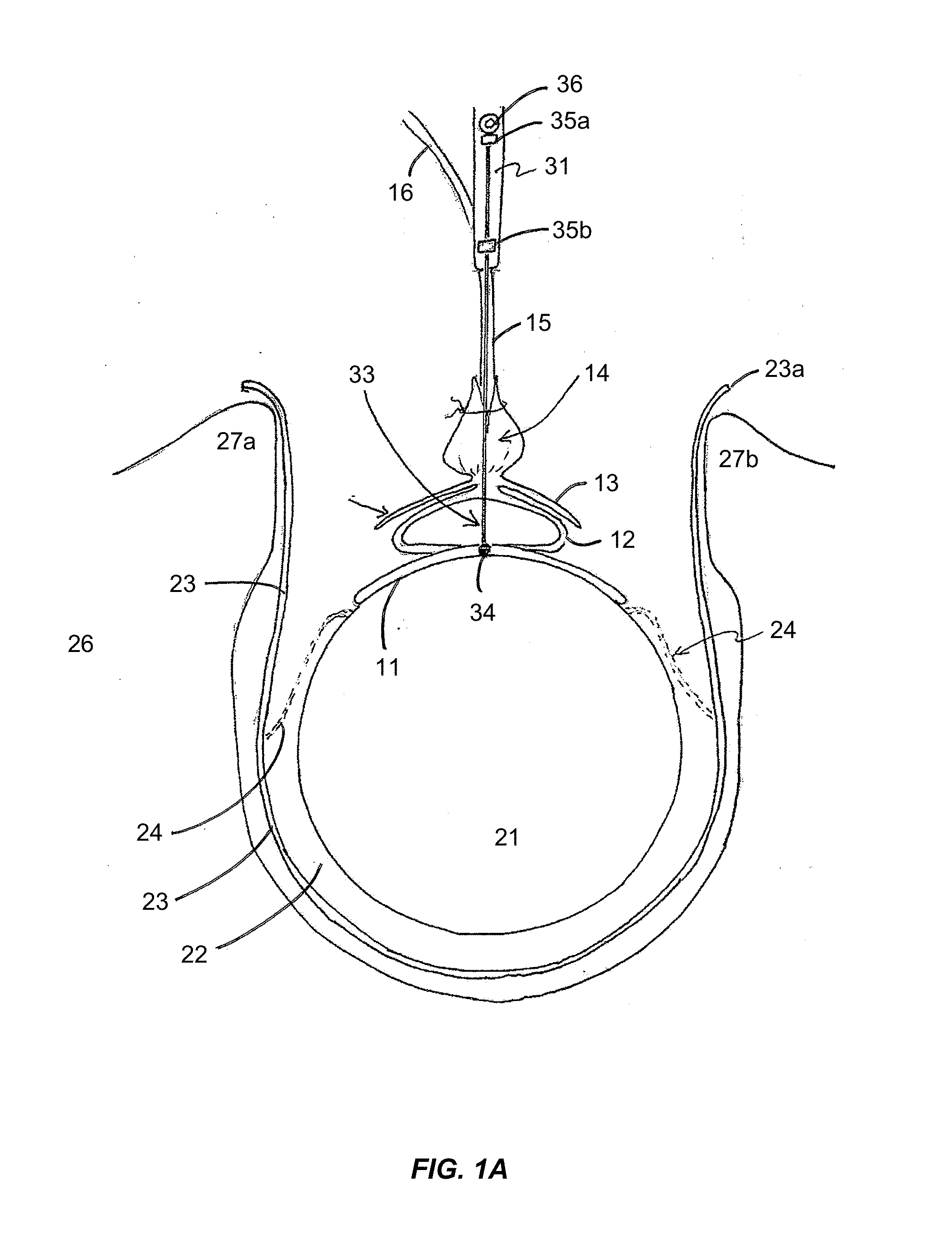
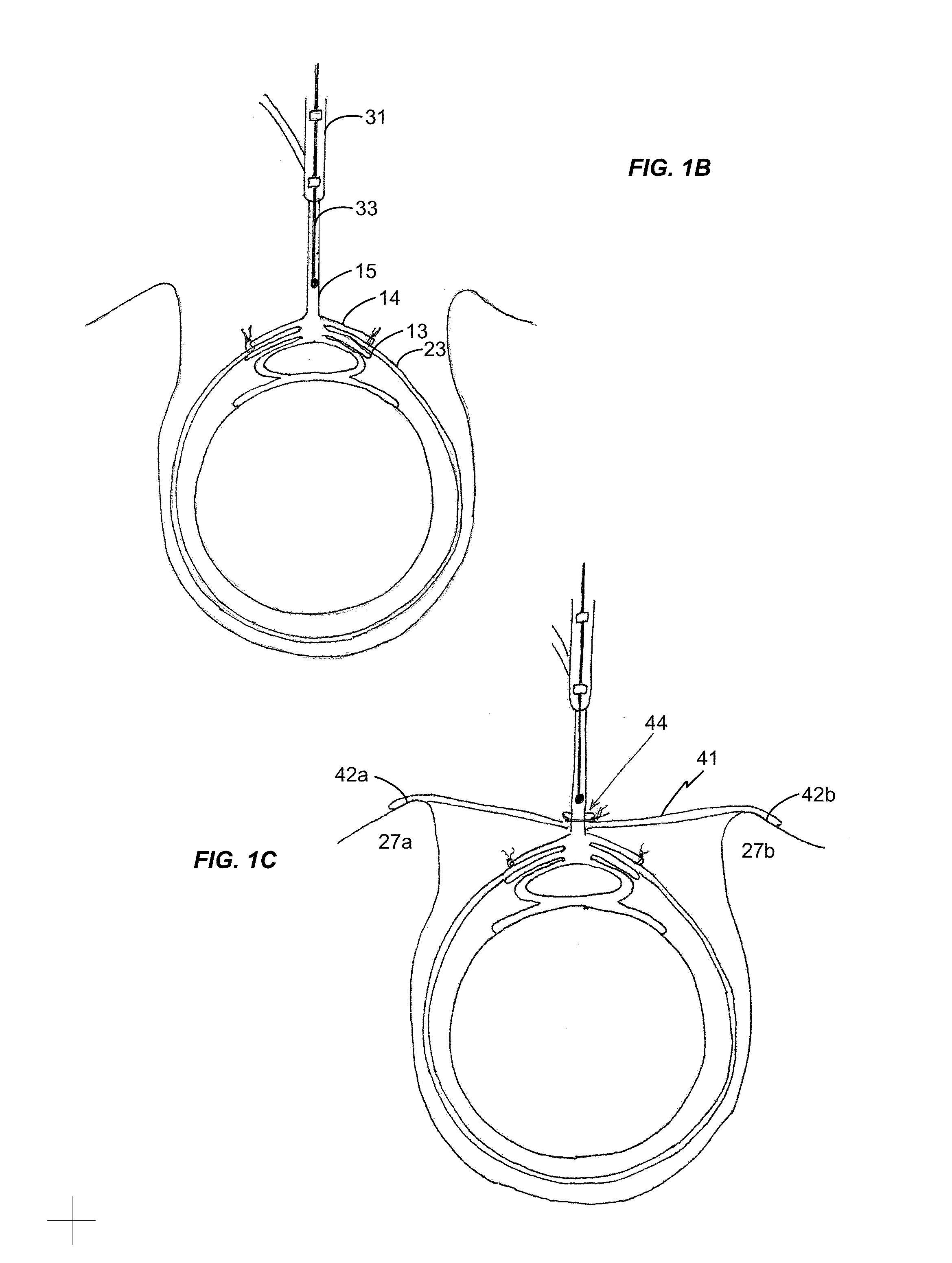
This invention provides a device for implantation directly into the spinal cord for the purpose of treating back pain. Electrodes on a backing that conforms directly to the spinal cord are installed as a source of electrical stimulation and pain relief. The electrode array is maintained on the spinal cord at a chosen location by way of a spring or support structure that is anchored to an anatomical structure outside the spinal cord but near the site of implantation. Suitable anchoring structures include the vertebrae and the dura. Secured in this fashion, the support structure maintains a gentle pressure of the electrode array against the spinal cord so as to stay in electrical contact but minimize injury or inflammation. The device may accommodate and buffer movement of the spinal cord both laterally and in a caudal-rostral fashion so that the electrode array remains in place.

Description

REFERENCE TO RELATED APPLICATIONS[0001]This application is the U.S. National Stage of International Application PCT / US2013 / 023912, filed Jan. 30, 2013, which was published as WO 2013 / 116377 on Aug. 8, 2013. This application claims the priority benefit of U.S. provisional application 61 / 592,515, filed Jan. 30, 2012; and U.S. provisional application 61 / 592,520 filed Jan. 30, 2012.[0002]The priority applications and published PCT application WO 2012 / 065125 are hereby incorporated herein by reference in their entirety for all purposes.FIELD OF THE INVENTION[0003]The invention relates generally to the field of medical devices and pain management. In particular, it provides electrode arrays and support structures for electrical stimulation of the spinal cord.BACKGROUND[0004]Chronic pain is an often unbearable sequelae of spinal cord injury or disease. It can interfere with the basic activities, effective rehabilitation, and quality of life of the patient. The prevalence of pain in patient...

Claims


Application Information

Patent Timeline
IPC IPC(8): A61N1/05A61N1/36
CPCA61N1/0558A61N1/36071A61N1/0553A61N1/36171F04C2270/0421
Inventor HOWARD, MATTHEW A.OYA, HIROYUKIVILJOEN, STEVEREDDY, CHANDAN G.
Owner UNIV OF IOWA RES FOUND
Why Eureka
Try Eureka