
Controller and Method for Controlling Communication Services for Applications on a Physical Network

Active Publication Date: 2014-12-18
SIEMENS AG
View PDF8 Cites 41 Cited by
  • Summary
  • Abstract
  • Description
  • Claims
  • Application Information

AI Technical Summary

Benefits of technology

The present invention aims to improve the control of communication services on a physical network. It separates the planning of the network and its configuration, making it easier to improve network efficiency. The invention can handle multiple network elements and network architectures easily. By optimizing the mapping and calculation of virtual networks, the use of the physical network is improved.

Problems solved by technology

Current internet and local area network technologies cannot fulfill those requirements.
One problem with this procedure is the lack of flexibility under tight coupling of the application planning in network configuration and operation.
This may create extra costs due to manual re-planning.
Further, this may be error-prone.
Furthermore, it may be hard to use non-industrial technologies as a base for products in industrial networks.
In particular, the evolution of standard Internet / LAN technologies is difficult to be integrated within an industrial communication technology such as PROFINET.
One of these reasons is the required development costs in terms of hardware, like application specific integrated circuits (ASICs), such as the case within PROFINET.
Any technological improvement in the Institute of Electrical and Electronic Engineers (IEEE) standard Ethernet requires large development costs to integrate this extension within PROFINET.
Further, this might lead to several generations of the same protocol that potentially cannot interoperate.
In addition, the effect of a change on the standard might snow-ball, because PROFINET covers not only networking issues, but also end-devices, middleware and engineering tools that interact with the PROFINET-capable devices and networks.
In addition, mixing products from different standards, with sometimes very different capabilities in the same network, is typically difficult or not possible because conventional planning tools cannot work with heterogeneous standards.
A further problem is the fact that many applications from different stack holders may compete for resources and have to be shielded from each other for security and management reasons (multi-tenancy).
1) Use of different physical networks. This approach, while still commonly used, provides no flexibility and creates extra costs for hardware.
2) The use of virtualization combined with over-dimensioning of the network by setting up a pre-defined and static series of subnets and LANs around a given application (e.g., a control application of a factory cell). This cellular approach also may be less effective neither in allowing inter-cell communication nor in enabling rational network deployment.
3) Industrial extensions to Ethernet protocols to include needs of industrial communication. This solution, however, lacks flexibility, is not suited for interoperability, and has created specialized niche products that have evolved as standalone standards such as Profinet. Those industrial standards typically cannot shield non-industrial applications from each other and must use other means as described in publication [2] to do so.
4) Traffic engineering and Quality of Service (QoS) dimensioning of the network, which is the approach often found in telecommunication networks and used by internet service providers. This allows a certain control over the owned network that is providing communication as a service to multiple tiers. This approach is, however, not as appropriate to the industrial applications, due to the granularity and complexity in defining Service Level Agreements (SLAs) for each user. This approach is also based on some protocols and specified for larger hardware (such as routers supporting RSVP, or MPLS switches). Thus, existing technologies cannot be used for industrial networks, here.

Method used


Image

  • Controller and Method for Controlling Communication Services for Applications on a Physical Network
  • Controller and Method for Controlling Communication Services for Applications on a Physical Network
  • Controller and Method for Controlling Communication Services for Applications on a Physical Network

Examples


first embodiment

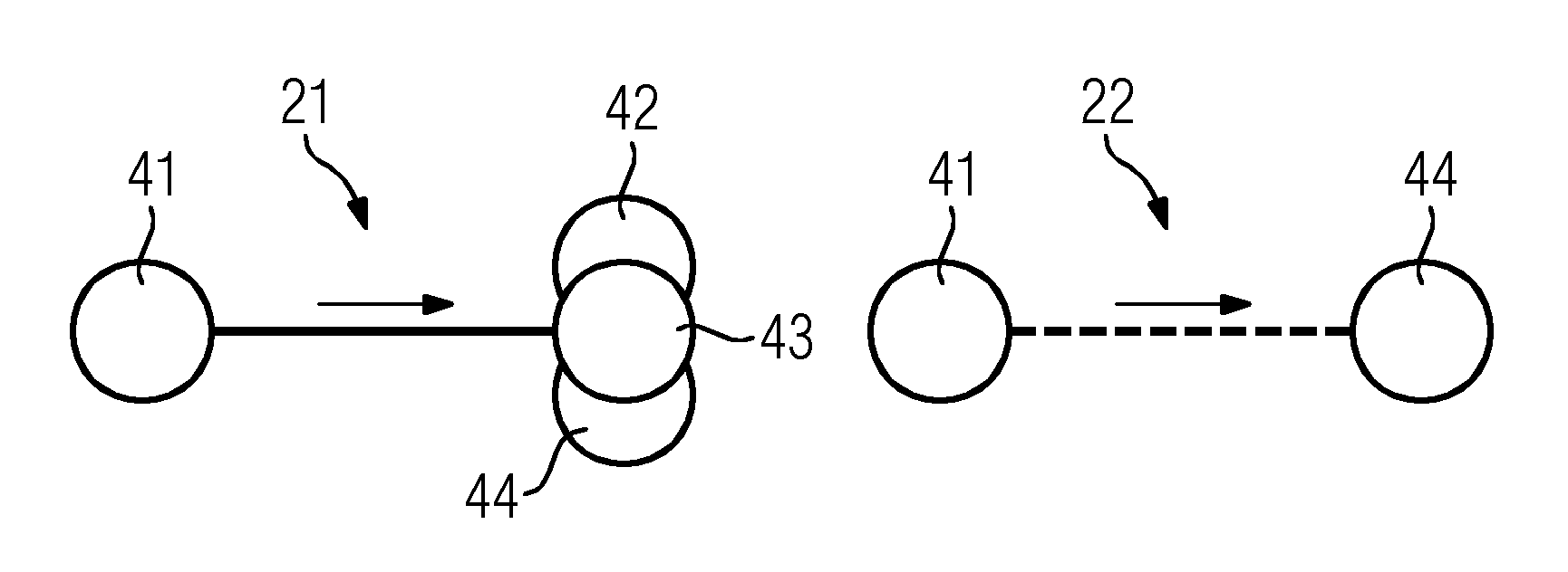
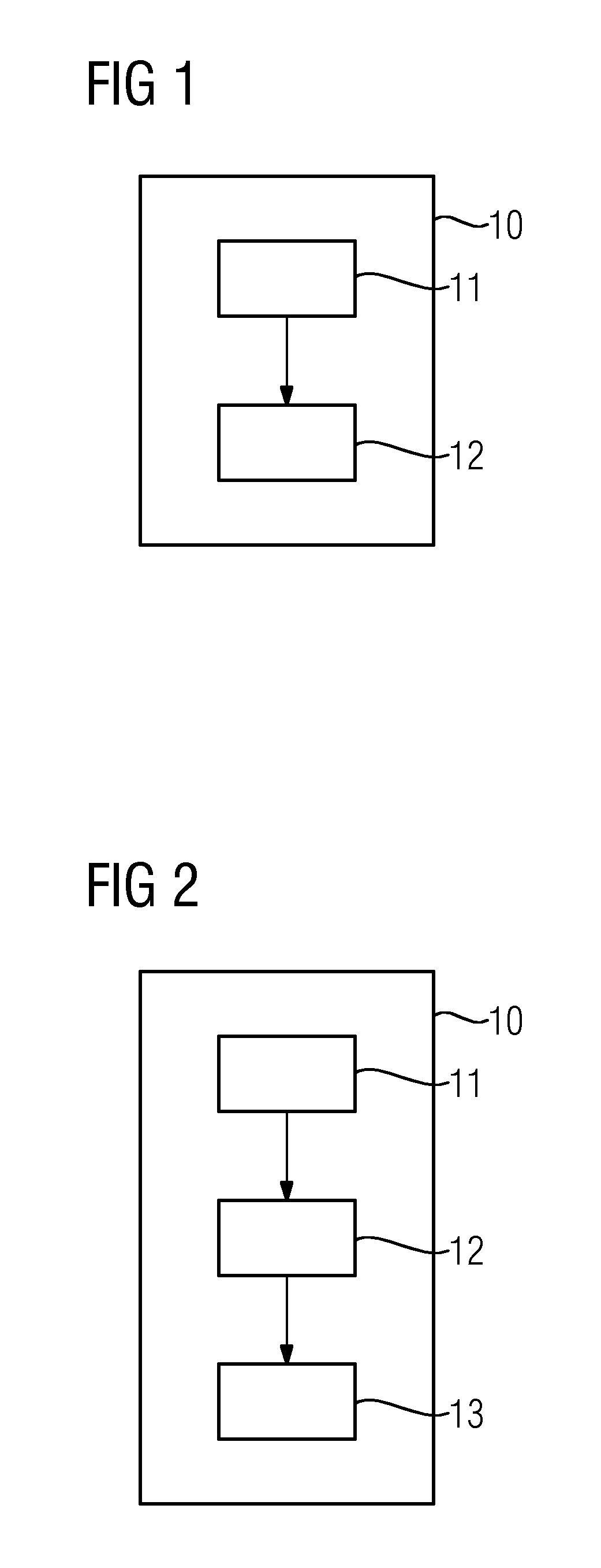
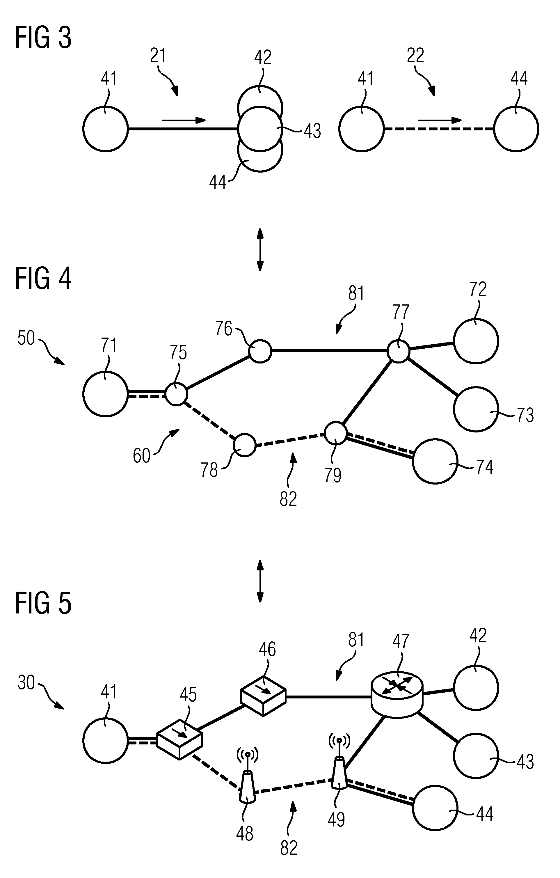
[0067]FIG. 1 shows a schematic block diagram of a controller 10 for controlling communication services for a plurality N of applications 21, 22 on a physical network 30 having a plurality M of network nodes 41-49 providing certain network resources. Each of the N applications 21, 22 is described by a set of requirements and is configured to run on at least two of the M network nodes 41-49. In the following, the controller 10 of FIG. 1 is discussed with reference to FIGS. 3 to 5. In this regard, FIG. 5 shows an embodiment of a physical network 30, FIG. 4 a network model 50 of the physical network 30 of FIG. 5, and FIG. 3 shows two exemplary applications 21, 22 that are to be implemented in the physical network of FIG. 5.

[0068]With respect to FIG. 3, and without loss of generality, N=2 in this example. Further, with reference to FIGS. 4 and 5, M=9 without loss of generality.

[0069]FIG. 3 shows two applications 21, 22, where the first application 21 has four end devices 41-44 between wh...

third embodiment

[0079]Moreover, the requestor 15 is configured to request network information on the network resources from the physical network 30 and node information on the node capabilities and the node resources from the network nodes 41-49. In this third embodiment, the generator 30 may be configured to generate the network model 50 based on the network information and the node information as requested by the requestor 15.

[0080]FIG. 7 shows a method for controlling communication services for a plurality N of applications 21, 22 on the physical network 30 having a plurality M of network nodes 41-49 providing certain network resources. Each of the N applications 21, 22 is described by a set of requirements and is configured to run on at least two of the M network nodes 41-49.

[0081]The method of FIG. 7 includes the following steps 101-103:

[0082]In step 101, a network model 50 of the physical network 30 is generated. The network model 50 includes a topology 60 of the physical network 30 and a nod...


PUM


Abstract

A method, computer program product and controller for controlling communication services for a plurality of applications on a physical network having a plurality M of network nodes providing certain network resources, wherein each of the applications is described by a set of requirements and is configured to run on at least two of the network nodes. The controller includes a generator and a calculator. The generator generates a network model of the physical network including a topology of the physical network and a node model for each of the network nodes, where the node model describes node capabilities and node resources of the network node. The calculator calculates virtual networks for the applications by mapping each respective set of requirements of the applications to the generated network model, where each of the calculated virtual networks includes at least two network nodes and a slice of the certain network resources.

Description

REFERENCE TO RELATED APPLICATIONS[0001]This is a U.S. national stage of application No. PCT / EP2013 / 051401 filed 25 Jan. 2013. Priority is claimed on European Application No. 12000488.2 filed 26 Jan. 2012, the content of which is incorporated herein by reference in its entirety.BACKGROUND OF THE APPLICATION[0002]1. Field of the Invention[0003]The present invention relates communication networks and, more particularly, to a controller and a method for controlling communication services for applications on a physical network.[0004]2. Description of the Related Art[0005]Many networks particularly require a predictable operation with precise timings and a high level of reliability. This is especially true for industrial networks. In this regard, “industrial network” preferably refers to Ethernet / IP-based networks in factory automation, traffic control, machine-to-machine, Supervisory control and data acquisition (SCADA) application areas.[0006]Current internet and local area network tech...

Claims


Application Information

Patent Timeline
IPC IPC(8): H04L12/24H04L29/08
CPCH04L41/12H04L67/10H04L41/50H04L41/145H04L41/5054G05B2219/24215
Inventor HOUYOU, AMINE MOHAMEDHUTH, HANS-PETER
Owner SIEMENS AG
Learn More