Capacitor-type welding device and capacitor-type welding method

a welding device and capacitor technology, applied in welding electric supplies, metal working devices, manufacturing tools, etc., can solve the problems of large backflow current due to magnetic energy, difficult control of charging circuits, etc., and achieve the effect of reducing electric power loss and cos

Active Publication Date: 2014-12-25
ORIGIN ELECTRIC CO LTD
View PDF4 Cites 7 Cited by
  • Summary
  • Abstract
  • Description
  • Claims
  • Application Information

AI Technical Summary

Benefits of technology

[0016]The capacitor type welding device and the control method therefor according to the present invention can prevent the disablement of the control to the thyristors in the charging circuit under the influences of the backflow current, achieve the downscaling, reduce the electric power loss, and attain the cost reduction.

Problems solved by technology

If this occurs, the backflow current due to the magnetic energy may become also large, a certain thyristor in the hybrid bridge full wave rectifier circuit may not be able to become a non-conduction state but keep the conduction state.
Then, the desired control of the charging circuit becomes difficult.

Method used


Image

  • Capacitor-type welding device and capacitor-type welding method
  • Capacitor-type welding device and capacitor-type welding method
  • Capacitor-type welding device and capacitor-type welding method

Examples


first embodiment

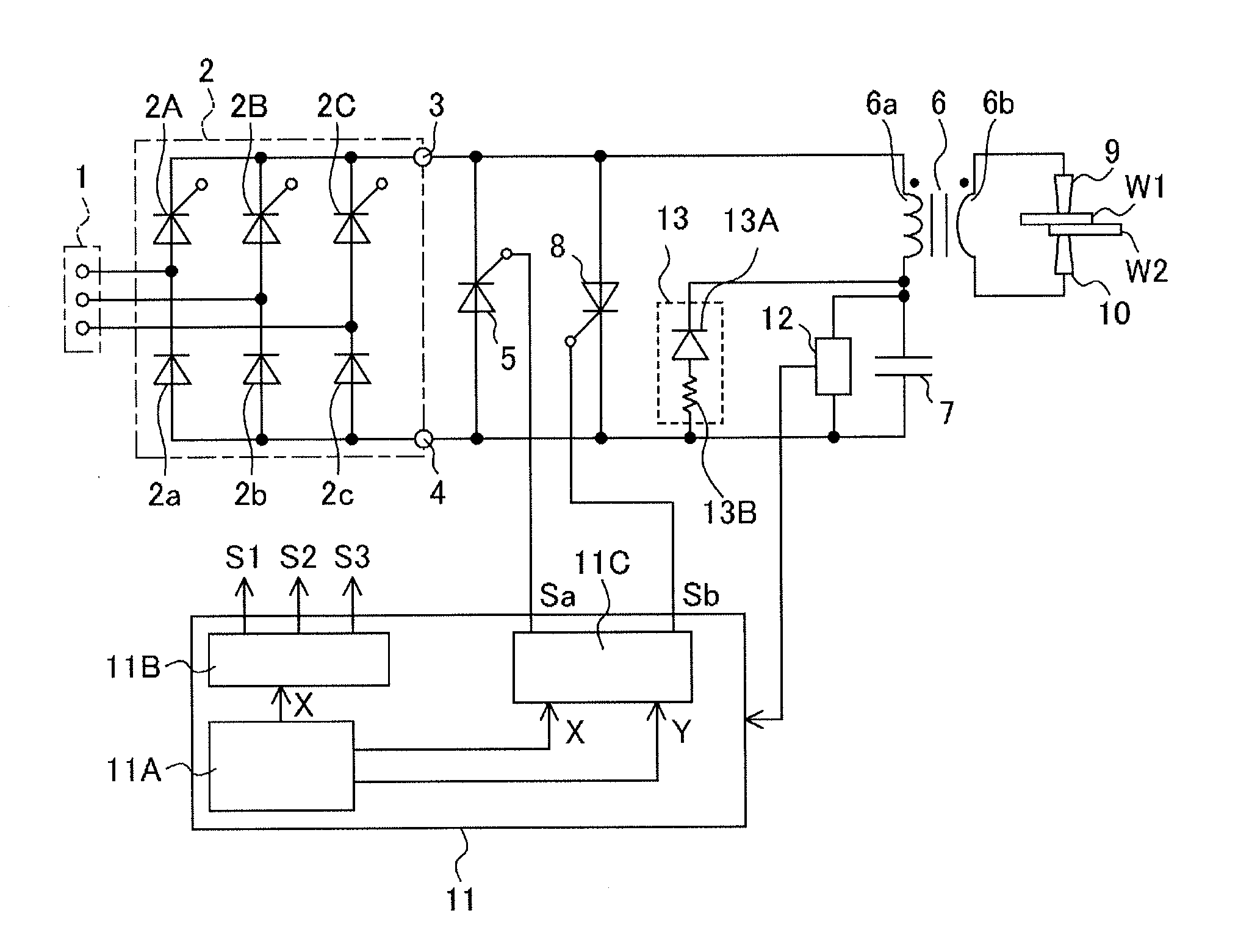
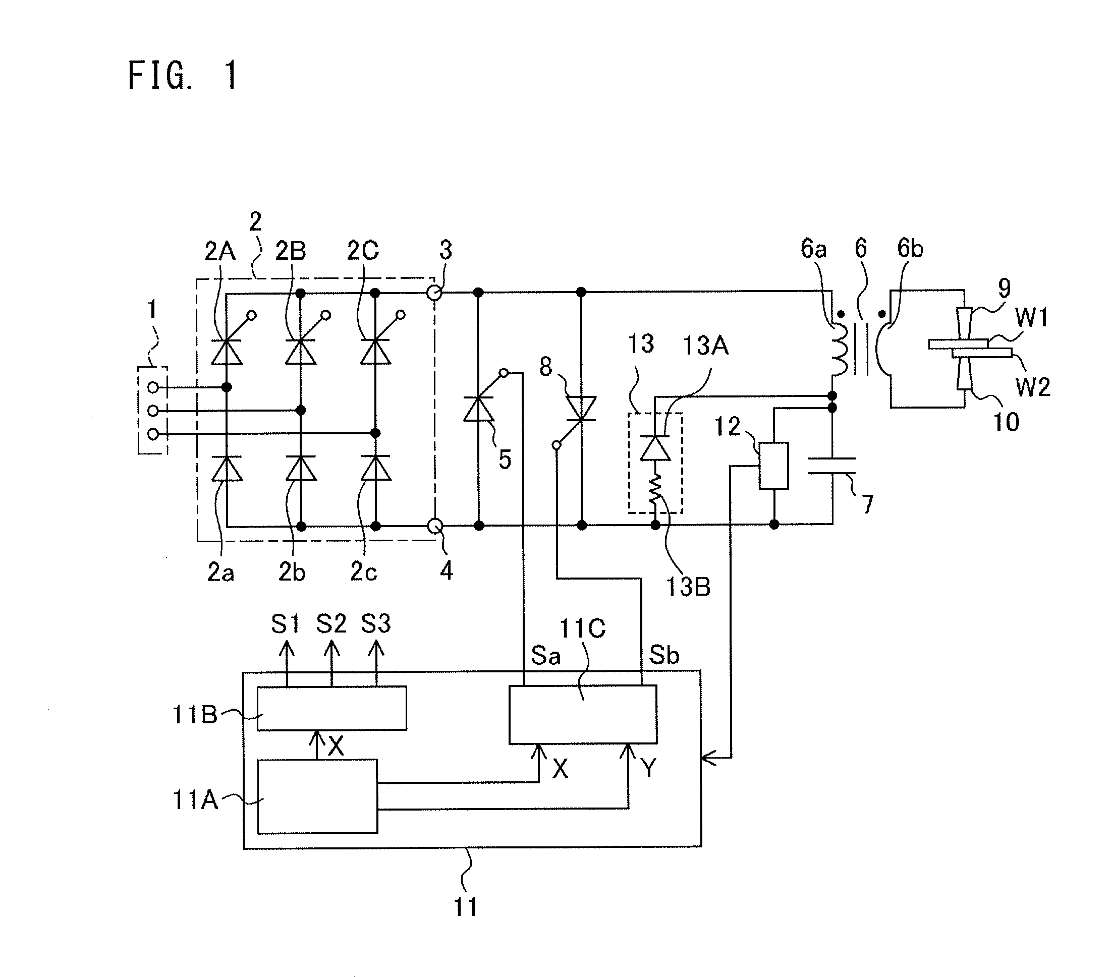
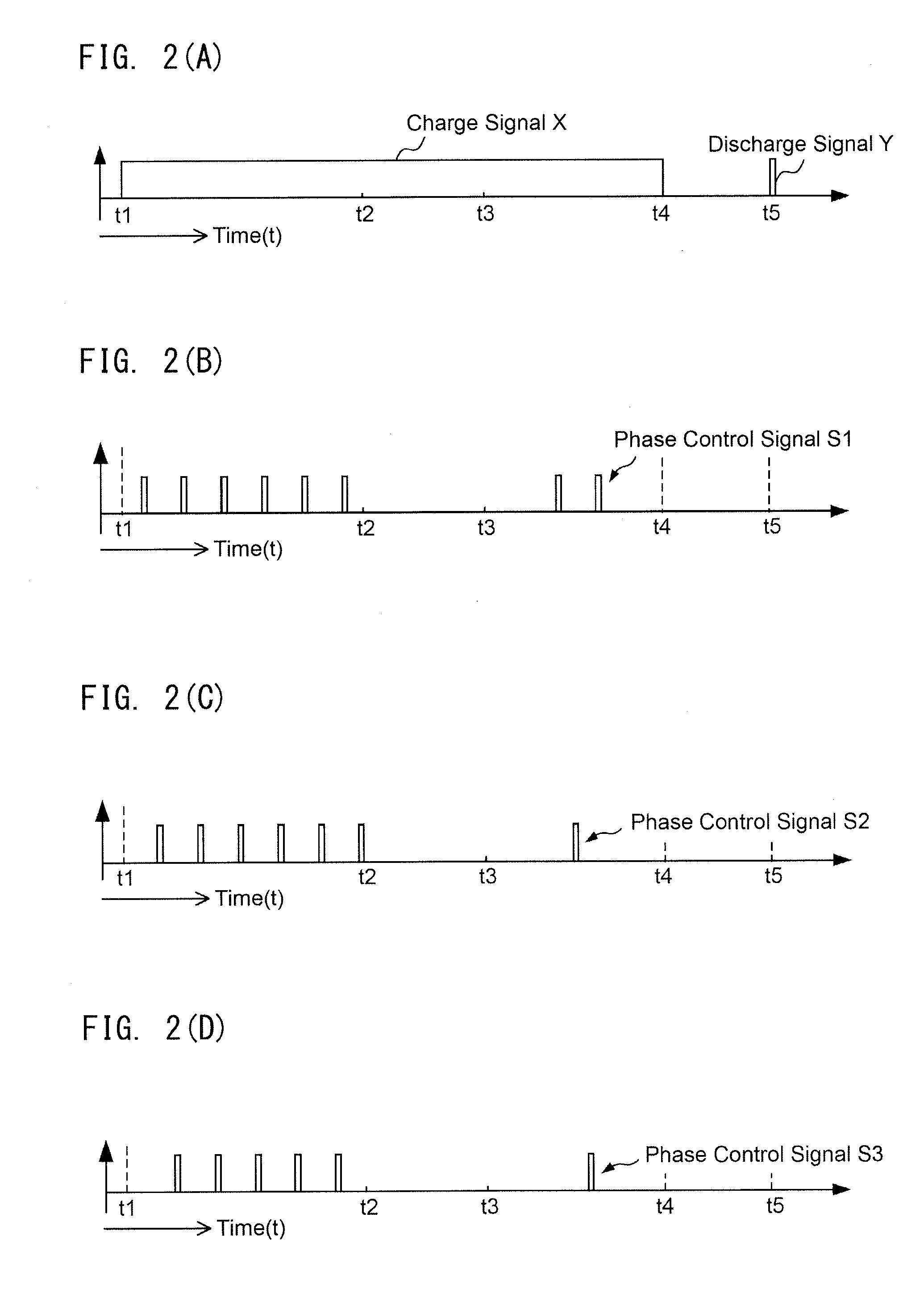
[0028]Referring to FIGS. 1 and 2, the capacitor type welding device and the capacitor type welding method according to the first embodiment of the present invention will be described. The capacitor type welding device shown in FIG. 1 includes a three-phase AC input terminal 1, a charging circuit 2, DC output terminals 3 and 4 of the charging circuit 2, a bypass switching element 5 connected across the DC output terminals 3 and 4, a welding transformer 6 having a primary winding 6a and a secondary winding 6b, a welding capacitor 7, a discharge switch 8, a first welding electrode 9, a second welding electrode 10, and a control circuit 11. The first and second welding electrodes 9 and 10 are connected to the secondary winding 6b.

[0029]The control circuit 11 sends control signals S1, S2 and S3 to the charging circuit 2, sends a first drive signal Sa to the bypass switching element 5, and sends a second drive signal Sb to the discharge switch 8. A voltage detecting circuit (voltage dete...

second embodiment

[0057]Referring now to FIG. 3, a capacitor type welding device and a capacitor type welding method according to a second embodiment of the present invention will be described. Major differences in the circuitry of the second embodiment, when compared to the first embodiment, lie in that an inductor 14 for improving a power factor is connected between the charging circuit 2 and the welding capacitor 7 to improve the charging efficiency, the discharge switch 8 is connected in series to the primary winding 6a of the welding transformer 6, and the welding capacitor 7 is connected in parallel to the series circuit constituted by the primary winding 6a and the discharge switch 8.

[0058]Similar to the first embodiment, the bypass thyristor 5 is connected in parallel to the charging circuit 2, with the cathode of the bypass thyristor 5 being connected to the DC output terminal 3 of the charging circuit 2 and the anode being connected to the DC output terminal 4 of the charging circuit 2. Sim...


PUM

PropertyMeasurementUnit
timeaaaaaaaaaa
holding currentaaaaaaaaaa
charging currentaaaaaaaaaa

Abstract

An economical capacitor-type welding device and capacitor-type welding method that have a small power loss, that can be made compact, and that reliably control a charging circuit without being affected by the inductance of a charging path. In an exemplary capacitor-type welding device and an exemplary capacitor-type welding method of the invention, a bypass switching element having a forward-blocking function is connected in parallel to output terminals of a charging circuit, and the bypass switching element is brought into a conduction state to allow a backflow current, which is caused to flow by a magnetic energy stored in the inductance of a primary winding or an inductor included in the charging path, to bypass the charging circuit. A discharge switching element is brought into a conduction state after the bypass switching element enters the non-conduction state and recovers the forward-blocking function.

Description

TECHNICAL FIELD[0001]The present invention relates to a capacitor type welding device (capacitive welding apparatus) and a capacitor type welding method that weld an object (or objects) to be welded by discharging an energy, which is stored in a welding capacitor using a charging circuit, between welding electrodes in a short time via a welding transformer.BACKGROUND ART[0002]A capacitor type welding device is advantageous in that the capacitor type welding device does not need a large facility for receiving electric power, if compared to a general AC welding device, because the capacitor type welding device stores welding electric power in a welding capacitor in a longer time than a discharge time and discharges the electricity at once. The capacitor type welding device is also advantageous in that welding marks (burning) are hardly created at welded portions and distortions are small because the object(s) to be welded is (are) only superheated to a small extent. Because of such ad...

Claims


Application Information

Patent Timeline
Patent Type & Authority Applications(United States)
IPC IPC(8): B23K11/26
CPCB23K11/26B23K11/115B23K11/245B23K2101/18H02M1/32
Inventor ARAI, KOUJIKADOYA, YASUOKOMATSU, AKIO
Owner ORIGIN ELECTRIC CO LTD
Why Eureka
Try Eureka