Turbocharger

a turbocharger and turbocharger technology, applied in the field of turbocharger systems, can solve the problems of engine power loss, engine and air flow mass through the compressor may slow down, and the turbocharger continues to spin, so as to improve the torque/power output density of the engine and increase the flow of air into the engin

Inactive Publication Date: 2014-12-25
FORD GLOBAL TECH LLC
View PDF37 Cites 18 Cited by
  • Summary
  • Abstract
  • Description
  • Claims
  • Application Information

AI Technical Summary

Benefits of technology

[0003]Engines may use a turbocharger to improve engine torque/power output density. In one example, a turbocharger may include a compressor and a turbine connected by a drive shaft, where the turbine is coupl

Problems solved by technology

The reversal of air flow may cause the engine to lose power.
During tip-out surge, the engine and the air flow mass through the compressor may slow down, while the turbocharger continues to spin due to inertia and delays through the exhaust system.
The spinning compressor and low air flow rate may cause rapid pressure build-up on the compressor outlet, while the lagging higher exhaust flow rate may cause pressure reduction on the turbine side.
When forward flow through the compressor can no longer be sustainable, a momentary flow reversal occurs, and the compressor is in surge.
High levels of EGR m

Method used


Image

  • Turbocharger
  • Turbocharger
  • Turbocharger

Examples


second embodiment

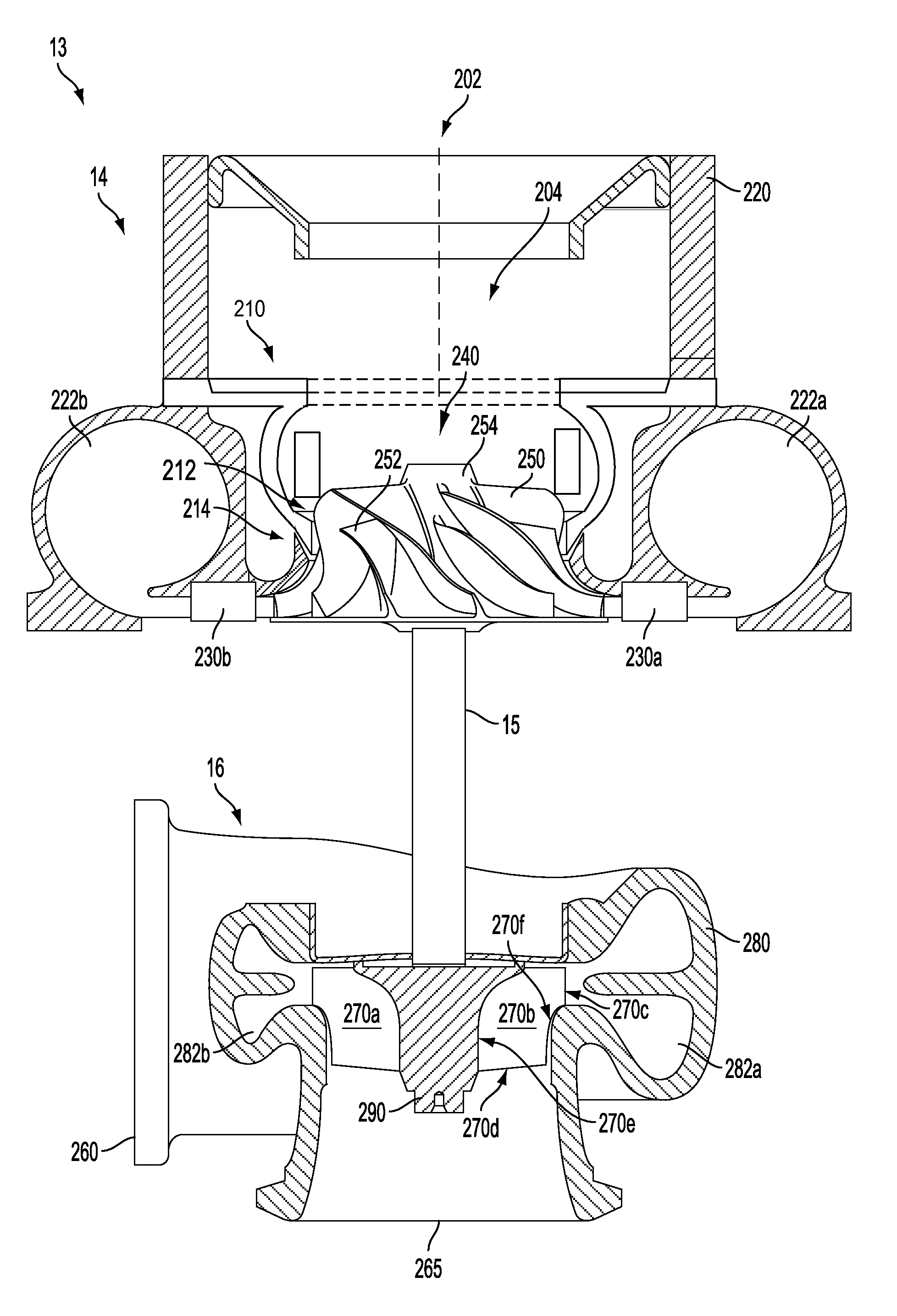
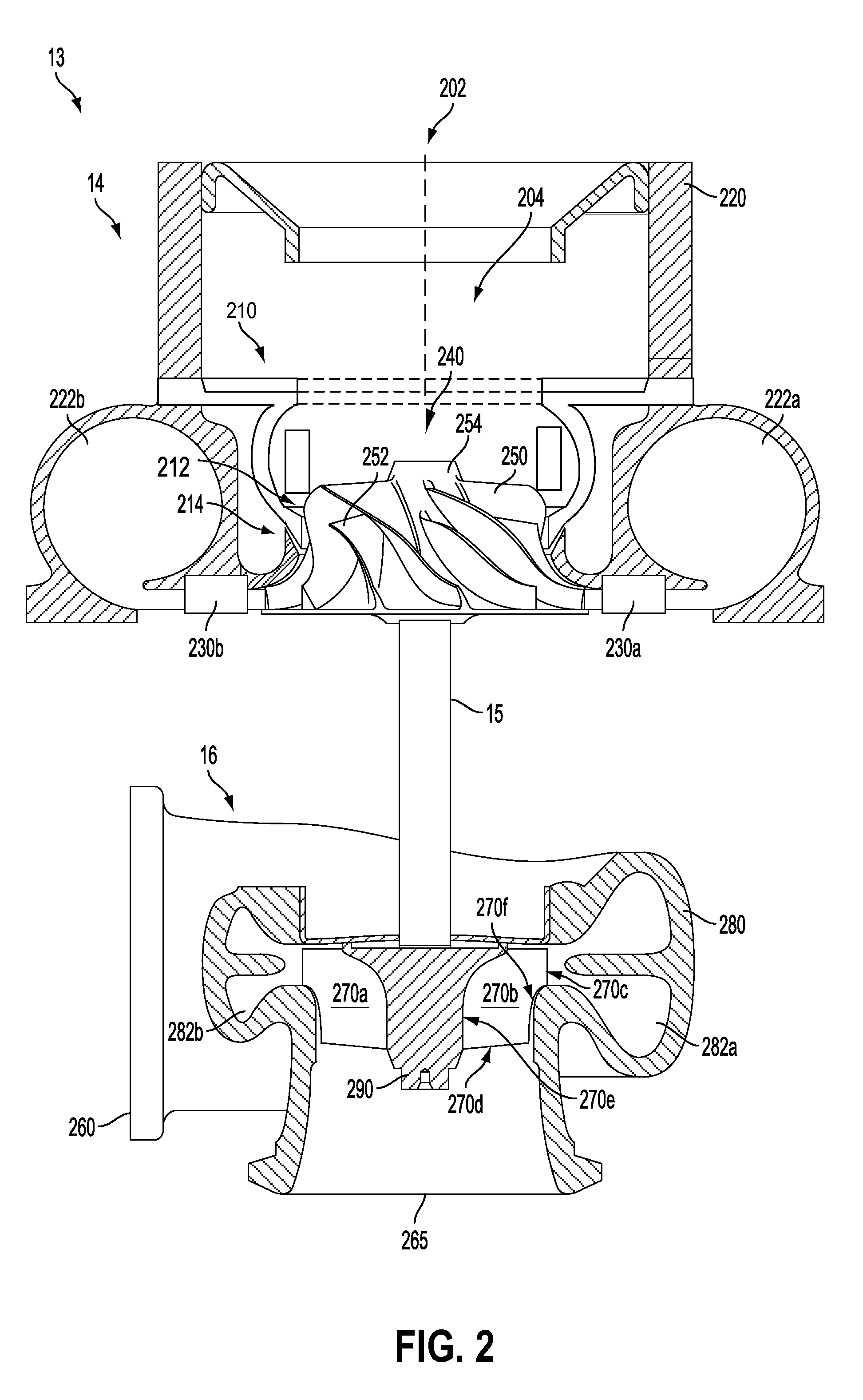
[0055]FIG. 8 shows a perspective view of a compressor 14 from an inlet side. The compressor inlet 202 is formed in inlet piece 221 of compressor casing 220. The inlet piece 221 in the second embodiment incorporates an integral housing 901 for a choke slot controller 408. As described above in reference to FIG. 3 an actuator may control a choke slot controller, the actuator may be a vacuum, pneumatic, or electric actuator. Lever arm 410 may be connected to such an actuator (not shown in FIG. 8). Movement of the actuator may be translated to lever arm 410 causing an actuator pin 412 to rotate actuatable annular disk 902 relative to outer annular disk 906. This rotation of the actuatable annular disk 902 may result in alignment of choke slots 904 with the choke slots of the outer annular disk 906. The choke slots 904 of the present embodiment are shown as rectilinear as opposed to the circular choke slots described above. It should be appreciated that the choke slots may take any confi...

first embodiment

[0063]The outer annular disk 906 of the present embodiment may comprise a greater extent of the inner walls of a compressor casing treatment of the present disclosure than the first embodiment shown in FIGS. 3-7. The greater depth of the outer annular disk 906 provided in part by flange 924 may allow for the integration of these various components into the outer annular disk. However, it should be appreciated that a flatter annular disk, such as shown at 420 in FIG. 4 may be coupled with an outer compressor casing that comprises the inner walls analogous to the bleed port and inner casing to accomplish the goals of the present disclosure.

[0064]Turning now to FIG. 11, the actuatable annular disk 902 is shown with the choke slot controller 408. The actuatable annular disk 902 may be configured to rest within the inset portion 921 of the outer annular disk 906. A rotation limiter 938 may extend beyond the substantially circular circumference of the actuatable annular disk 902. The rota...


PUM


Abstract

Systems and methods are disclosed for a turbocharger compressor, the system comprising: an actuatable annular disk comprising choke slots therein; an outer annular disk comprising choke slots therein; and an actuator to rotate the actuatable annular disk relative to the outer annular disk to vary alignment of the choke slots of the actuatable annular disk and the outer annular disk. The actuator may be controlled by an engine controller responsive to operating conditions of the compressor and actuated to align choke slots. Alignment of the choke slots allows air to be drawn into the impeller effectively expanding the compressor flow capacity to prevent compressor choke.

Description

GOVERNMENT RIGHTS[0001]This invention was made with government support under DE-FC26-07-NT43280 awarded by the Department of Energy. The government has certain rights in the invention.TECHNICAL FIELD[0002]The present application relates to systems for turbochargers of internal combustion engines and control of compressor choke in some examples.BACKGROUND AND SUMMARY[0003]Engines may use a turbocharger to improve engine torque / power output density. In one example, a turbocharger may include a compressor and a turbine connected by a drive shaft, where the turbine is coupled to the exhaust manifold side and the compressor is coupled to the intake manifold side. In this way, the exhaust-driven turbine supplies energy to the compressor to increase the flow of air into the engine.[0004]The compressor is intended to work in an operating range between two conditions, surge and choke. Surge occurs during low air mass flow, when the air flow through the compressor stalls and may reverse. The ...

Claims


Application Information

Patent Timeline
IPC IPC(8): F04D27/02F04D29/46
CPCF04D29/464F04D27/0246F01D17/148F05D2220/40F02C6/12F02M26/05F02M26/06F04D27/0207F04D27/0215F04D29/4213F04D29/685
Inventor SUN, HAROLD HUIMINHANNA, DAVE R.POLLEY, THOMASHU, LIANGJUNKANTROW, DANIEL WILLIAM
Owner FORD GLOBAL TECH LLC
Why Eureka
Try Eureka