
Process-based approach for the detection of co2 injectate leakage

Active Publication Date: 2015-01-01
BOARD OF RGT THE UNIV OF TEXAS SYST
View PDF6 Cites 13 Cited by
  • Summary
  • Abstract
  • Description
  • Claims
  • Application Information

AI Technical Summary

Benefits of technology

The present invention provides a method for distinguishing between natural sources of deep gas and gas leaking from a CO2 storage reservoir at a near surface formation. The method involves measuring the levels of CO2, O2, CH4, and N2 in geological samples and determining the water vapor content. By comparing the measured levels of these gases to the levels in a natural source of deep gas or a gas leak, the method can identify the source of the gas. The method can be used in various geological environments and can be performed using gas chromatography. The presence of two or more ratios indicates gas leaking from the reservoir. The method can be used to distinguish between a natural source of deep gas and gas leaking from a CO2 storage reservoir at a near surface formation.

Problems solved by technology

A CO2 concentration-based approach has several drawbacks: (1) high variability of CO2 generated in situ could mask a moderate leakage signal; (2) 1 year of background characterization cannot account for CO2 variability from climatic, land use, and ecosystem variations over the lifetime (tens to hundreds of years) of a storage project; (3) background measurements require a long lead time potentially hindering a project's progress; and (4) background CO2 cannot be measured across all potential small diameter leak points within the area of review: therefore, if concerns arise in an area lacking local background measurements, no baseline data exist with which to compare monitored CO2 concentrations.

Method used


Image

  • Process-based approach for the detection of co2 injectate leakage
  • Process-based approach for the detection of co2 injectate leakage
  • Process-based approach for the detection of co2 injectate leakage

Examples


example 1

Novel Process-Based Leakage Detection

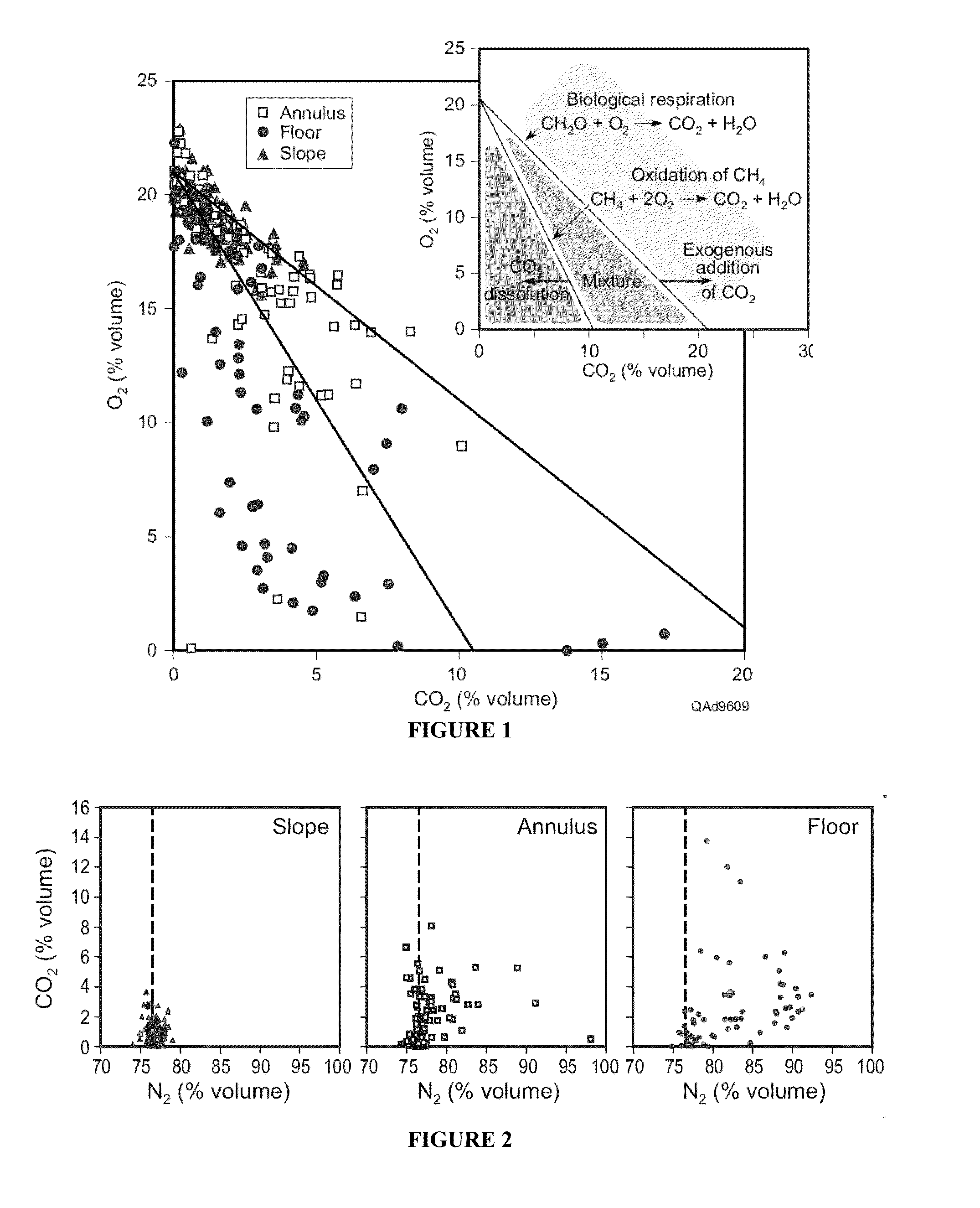
[0046]Study sites. The process-based leakage detection approach was developed at a natural CO2-rich ephemeral playa lake in west Texas, USA. Here, known vadose zone processes were coupled with their corresponding soil gas signatures. This information was then successfully applied at an oil field in Mississippi at the site of a plugged and abandoned well to identify anomalous near-surface CO2 and CH4 soil gas signals.

[0047]Playa Natural Analog. The playa lakes of west Texas are broad, gently sloping circular basins (˜1 to 2 km in diameter) that accumulate and transmit surface runoff through a thick (˜60 m) vadose zone. Geomorphic areas associated with playas, which include: slope, annulus, and floor, systematically differ in water flux, organic carbon content, and inorganic soil carbonate, creating spatial variability in the main factors that affect natural vadose zone CO2 production and consumption [Osterkamp and Wood, 1987; Romanak, 1997]. These...

example 2

Detection of Injectate Leakage from an Injected Reservoir

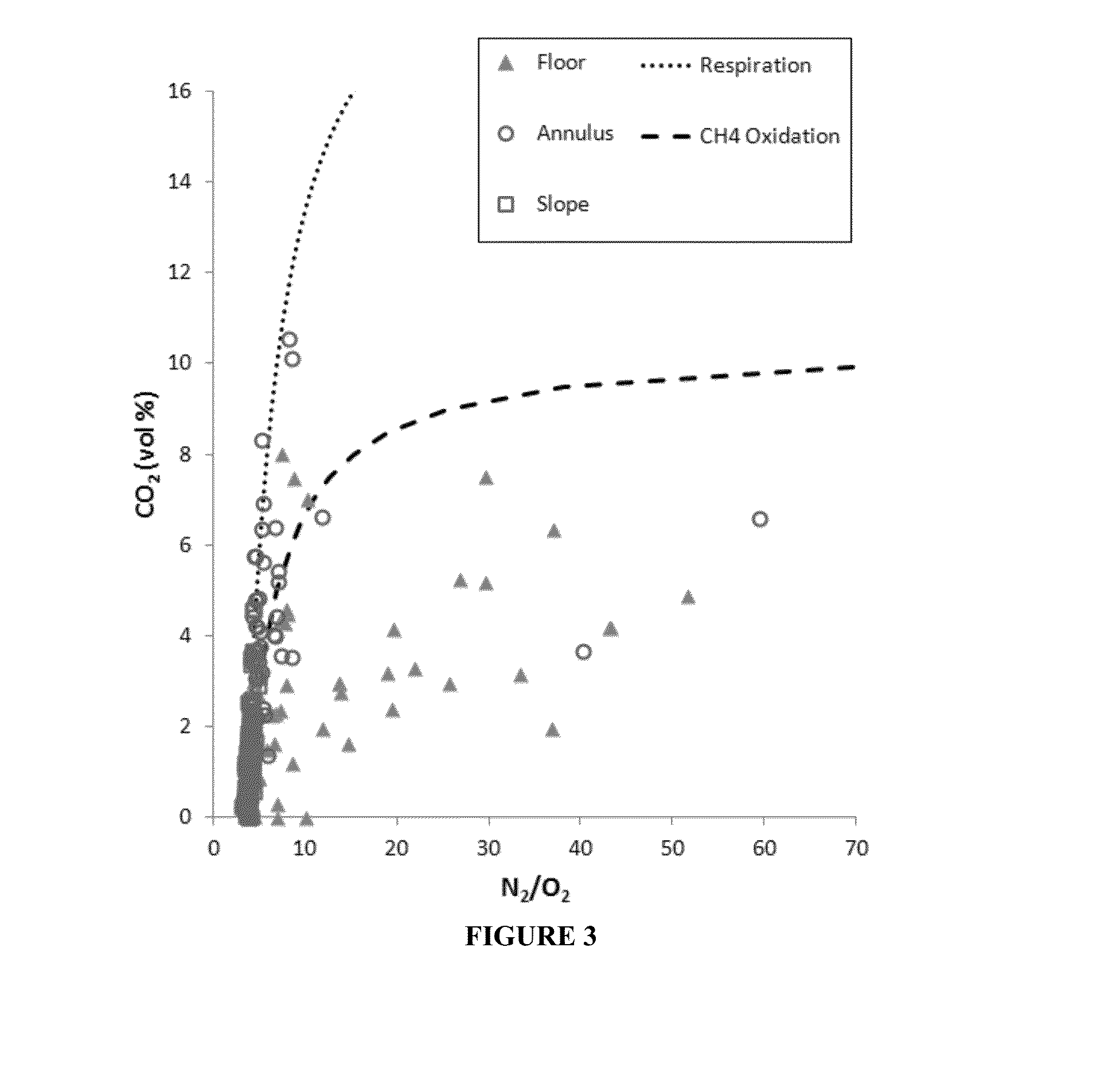
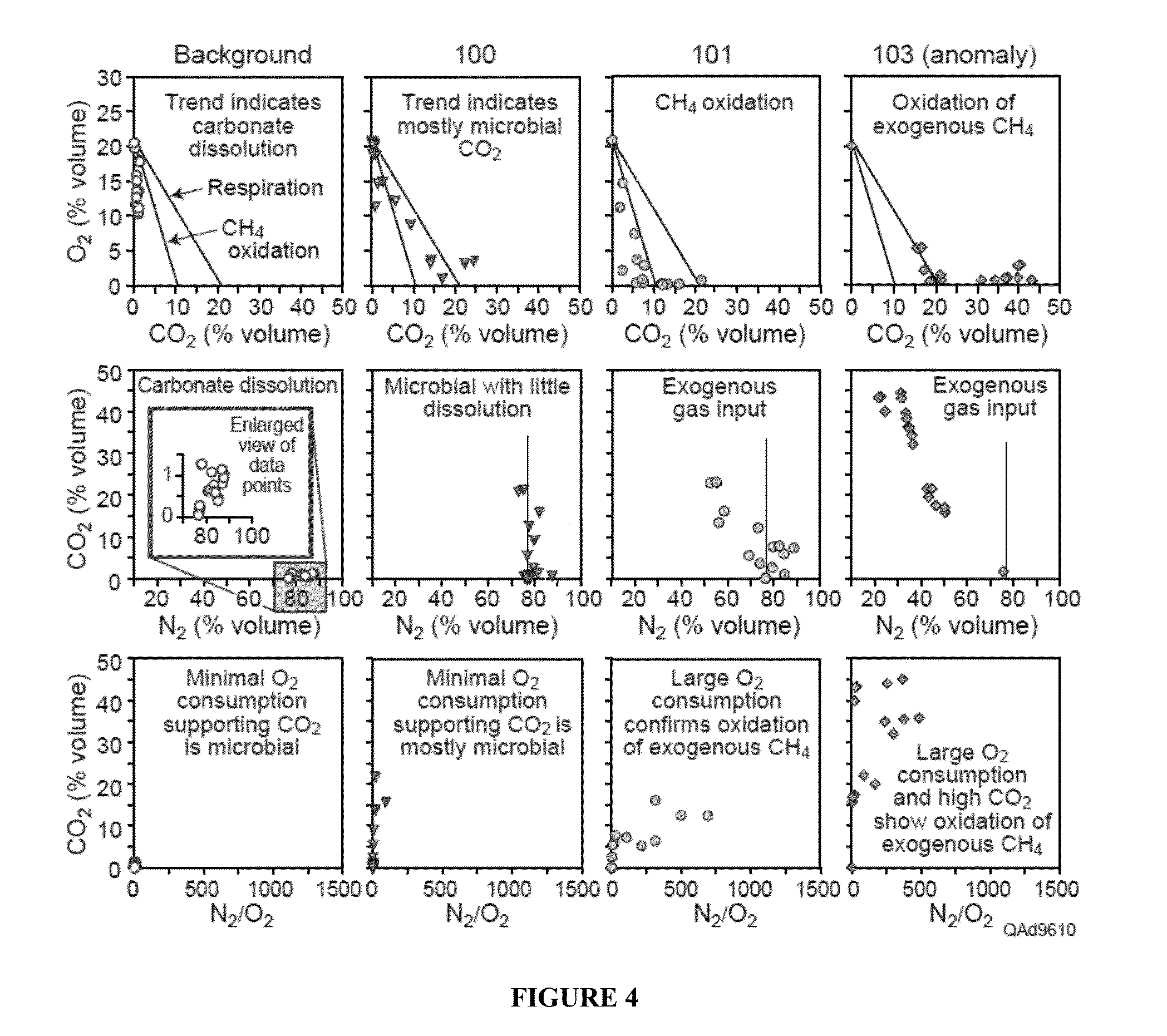
[0065]As shown in the insert of FIG. 1, the O2 vs. CO2 ratio gives an indication of the main natural processes affecting CO2 concentrations. It provides a preliminary distinction among respiration and CH4 oxidation (black lines and middle portion between the two lines, labelled mixture) or dissolution (bottom left area between the axis and the first line, labelled CO2 dissolution). It also gives an initial assessment of leakage (top right quadrant).[0066]1. Measure CO2 O2 CH4 N2 (and H2O vapor if possible).[0067]2. On a gas chromatograph, the O2 reading actually includes Ar. So is actually O2 and Ar. These gases are not separated.[0068]3. Calculate Argon (Ar) as equal to 1 / 63×N2 concentration.[0069]4. Subtract Ar from O2.[0070]5. Add water vapor content or assume saturated at 2.3%.[0071]6. Normalize to 1 atm total pressure or 100%.[0072]7. Observe relationships between O2 versus CO2 with respect to the processes of respiration...

examples 1 and 2

[0135]European Commission (2009), Directive 2009 / 31 / EC of the European Parliament and of the Council of 23 Apr. 2009 on the geological storage of carbon dioxide: Official Journal of the European Union L 140 / 114 EN.[0136]Fryar, A. E., S. A. Macko, W. F. Mullican, K. D. Romanak, and P. C. Bennett (2000), Nitrate reduction during ground-water recharge, Southern High Plains, Tex.: Journal of Contaminant Hydrology 40, 335-363.[0137]Furche, M., S. Schlömer, E. Faber, and I. Dumke (2010), One year continuous vadose zone gas monitoring above an EGR test site Geophysical Research Abstracts Vol. 12, EGU2010-3095-1, 2010 7th EGU General Assembly 2010.[0138]Gustayson, T. C., and D. A. Winkler (1988), Depositional facies of the Miocene-Pliocene Ogallala Formation, northwestern Texas and eastern New Mexico: Geology, 16(3): 203-206.[0139]Hanson, P. J., N. T. Edwards, C. T. Garten, and J. A. Andrews (2000), Separating root and soil microbial contributions to soil respiration: A review of methods an...


PUM

PropertyMeasurementUnit
depthaaaaaaaaaa
depthaaaaaaaaaa
depthaaaaaaaaaa

Abstract

The present invention includes a method for distinguishing between a natural source of deep gas and gas leaking from a CO2 storage reservoir at a near surface formation comprising: obtaining one or more surface or near surface geological samples; measuring a CO2, an O2, a CH4, and an N2 level from the surface or near surface geological sample; determining the water vapor content at or above the surface or near surface geological samples; normalizing the gas mixture of the CO2, the O2, the CH4, the N2 and the water vapor content to 100% by volume or 1 atmospheric total pressure; determining: a ratio of CO2 versus N2; and a ratio of CO2 to N2, wherein if the ratio is greater than that produced by a natural source of deep gas CO2 or deep gas methane oxidizing to CO2, the ratio is indicative of gas leaking from a CO2 storage reservoir.

Description

CROSS-REFERENCE TO RELATED APPLICATIONS[0001]This application claims priority to U.S. Provisional Application Ser. No. 61 / 840,234, filed Jun. 27, 2013, the entire contents of which are incorporated herein by reference.STATEMENT OF FEDERALLY FUNDED RESEARCH[0002]This invention was made with U.S. Government support by the U.S. Department of Energy through the Office of the Governor of Texas (contract DE-FG04-90AL65847) and the National Energy Technology Laboratory (contract DE FG26-05NT42590) through the Southeast Regional Carbon Sequestration Partnership. The government has certain rights in this invention.TECHNICAL FIELD OF THE INVENTION[0003]The present invention relates in general to the field of gas detection, and more particularly, to a novel process-based approach for the detection of injectate leakage from deep reservoirs.BACKGROUND OF THE INVENTION[0004]Without limiting the scope of the invention, its background is described in connection with detecting gas in the vadose zone...

Claims


Application Information

Patent Timeline
Patent Type & Authority Applications(United States)
IPC IPC(8): G01V9/00G01N33/00
CPCG01V9/00G01N33/0004G01M3/226G01N33/004G01N33/24Y02A50/20
Inventor ROMANAK, KATHERINEBENNETT, PHILIP C.
Owner BOARD OF RGT THE UNIV OF TEXAS SYST
Learn More