
Liquid level measuring device

a liquid level and measuring device technology, applied in the direction of instruments, machines/engines, television systems, etc., can solve the problems of short collection time of rivers, serious floods in urban regions, rapid flowing rivers, etc., and achieve the effect of reducing the installation cost of the liquid level measuring device, accurate and precise liquid level change measurement, and accurate realization

Inactive Publication Date: 2015-01-01
NATIONAL TAIWAN OCEAN UNIVERSITY
View PDF20 Cites 26 Cited by
  • Summary
  • Abstract
  • Description
  • Claims
  • Application Information

AI Technical Summary

Benefits of technology

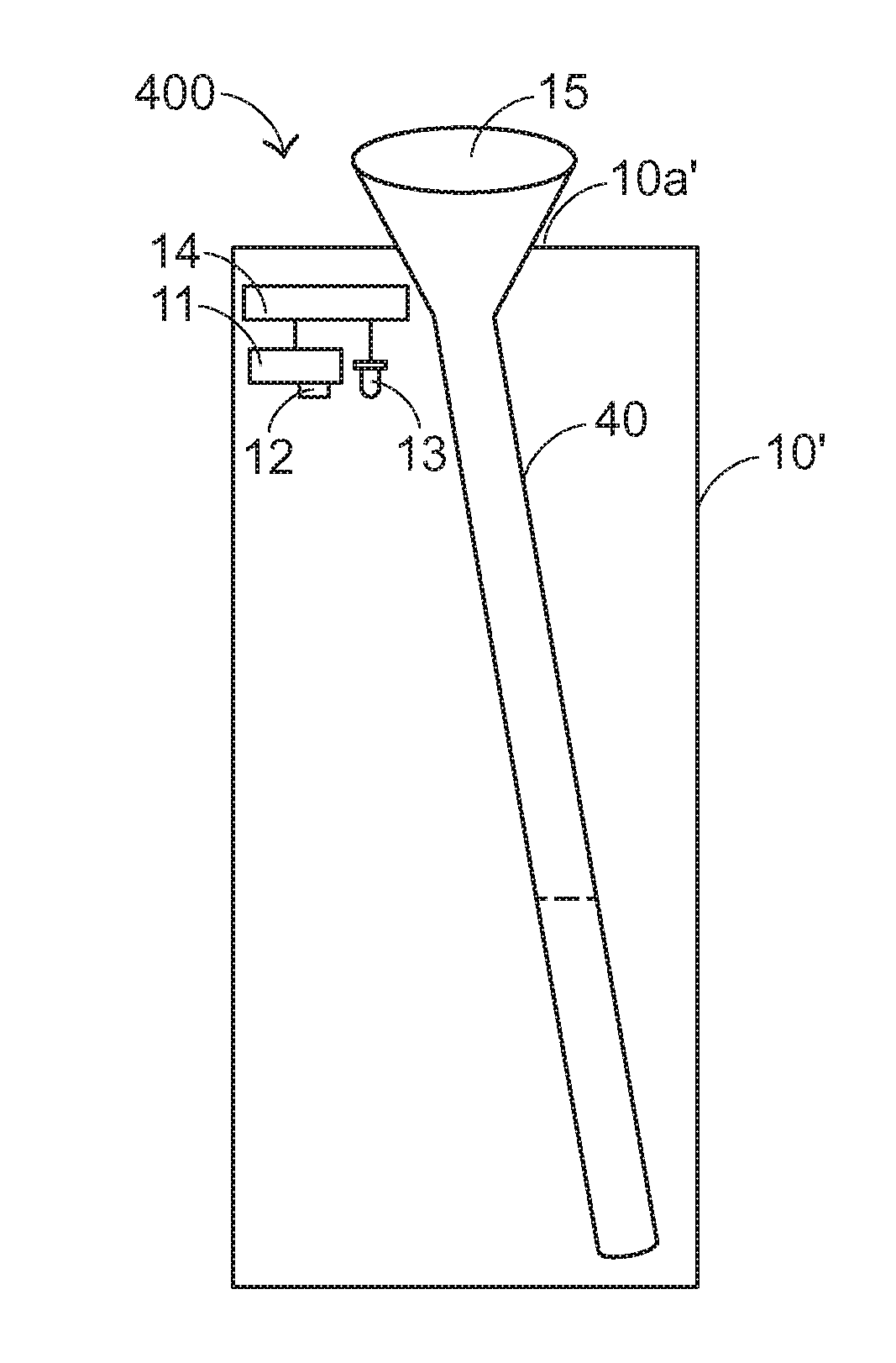
The present invention provides a liquid level measuring device that can accurately measure the change in liquid level in a detection region using an inclined partition structure and a light-transmission part. The device is made of an opaque material and has a sealed structure to prevent interference from ambient light beams. The device utilizes a digital electronic device and a light source for capturing and analyzing images, reducing installation cost and providing immediate images and information.

Problems solved by technology

As known, the steep terrain of the mountains in Taiwan may cause the rapid flowing rivers and short collecting time of the rivers.
If the hillsides are over-developed or the hydraulic facilities have not been installed before the flood season, the occurrence of heavy rainfall often causes landslides in mountains, serious flood in the urban regions, midstream and downstream of rivers, or other serious disasters.
Due to these meteorological factors, the possibility of causing natural disasters will increase.
However, these water level observation devices still have some drawbacks.
For example, since some of these devices are read by human judgment, the accuracy and the real-time measuring efficacy are usually unsatisfied.
In addition, some of these devices have high fabricating cost and thus fail to be widely installed.
Moreover, since some of these devices measure the water level by contacting the devices with water surfaces, it is difficult to maintain the devices.
However, the approaches of transmitting the observed data to a back-end device and processing the observed data in the back-end device are complicated.
Moreover, since the processes of capturing images are readily interfered by the ambient light beams, the results of the water level judgment are neither accurate nor precise.

Method used


Image

  • Liquid level measuring device
  • Liquid level measuring device
  • Liquid level measuring device

Examples


first embodiment

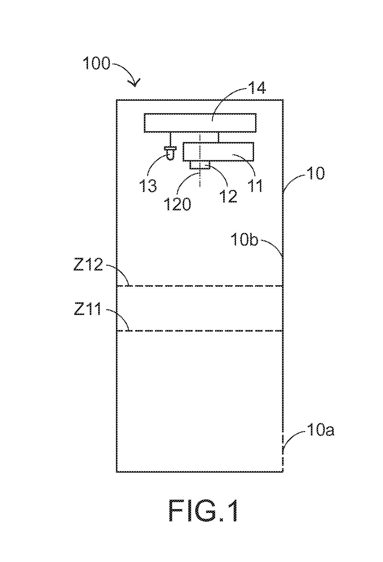
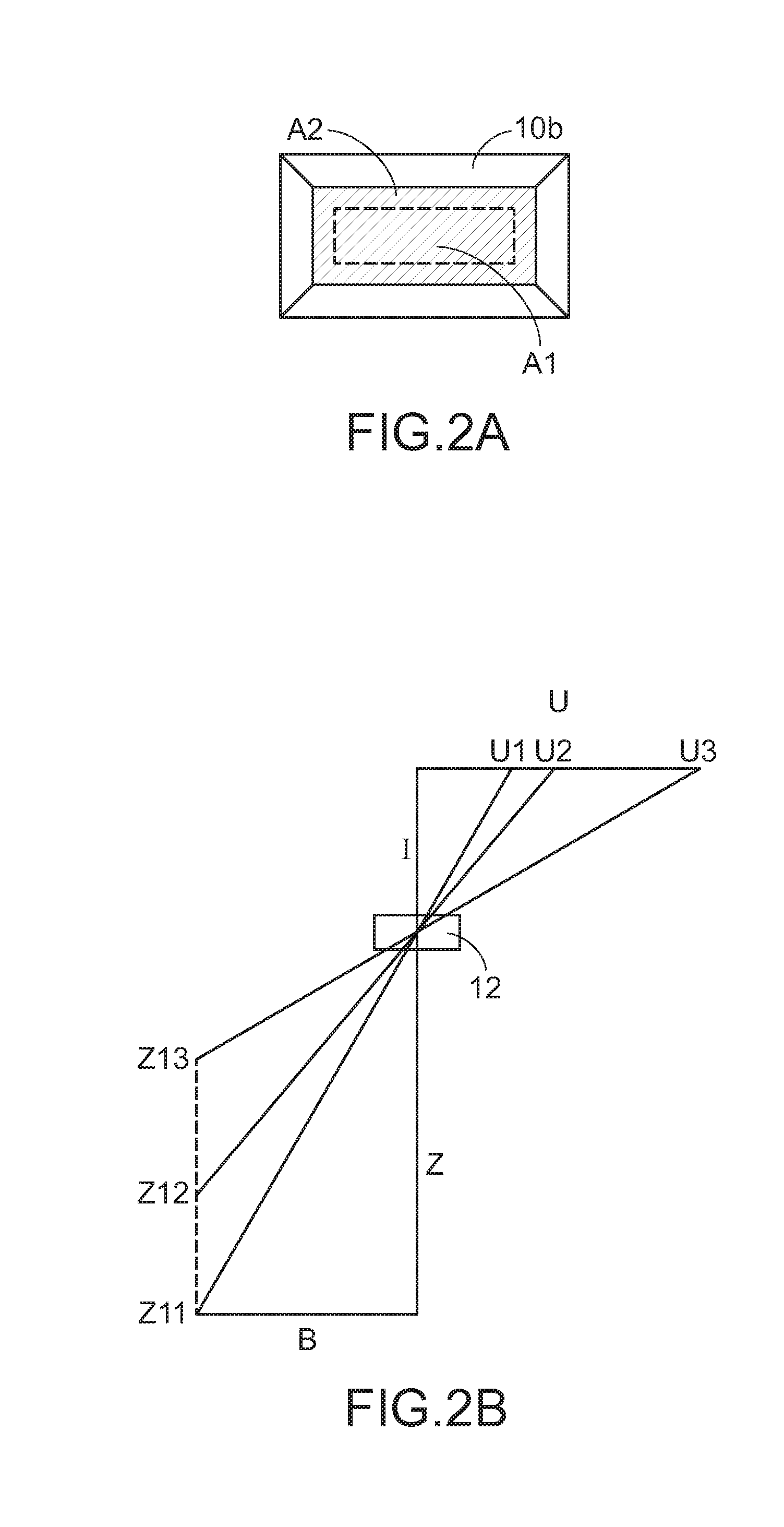
[0034]FIG. 2A schematically illustrates a continuous image-capturing result of the liquid level measuring device according to the present invention. Since the lens 12 is operated in the fixed focus mode, the size of the target region is fixed. That is, the image of the inner wall 10b contained in the image frame is unchanged. For example, in FIG. 1, two liquid levels Z11 and Z12 are shown. The liquid level Z11 indicates the liquid level at a first time point (e.g. an older time point) and corresponding to a liquid surface area A1 (see FIG. 2A). The liquid level Z12 indicates the liquid level at a second time point (e.g. a newer time point) and corresponding to a liquid surface area A2 (see FIG. 2A). In the image frame, the liquid surface area A2 is larger than the liquid surface area A1. That is, during the time interval between the first time point and the second time point, the liquid surface rises.

[0035]It is noted that the image frame at the first time point and the image frame ...

second embodiment

[0043]FIG. 3B is a schematic side view illustrating the partition structure of the liquid level measuring device according to the present invention. As shown in FIG. 3B, the partition structure 20 comprises a light-transmissible part 21 with a linear slope. In this embodiment, the light-transmissible part 21 is integrally formed with the partition structure 20. The light-transmissible part 21 is transparent. Whereas, the other surfaces of the partition structure 20 are deeply colored. In an embodiment, the partition structure is produced by a completely-transparent flat plate (e.g. an acrylic plate or a plastic plate) and then painting the flat plate with a deep color pigment, wherein only an oblique line with an inclined angle is not painted. The oblique line is served as the light-transmissible part 21. The light-transmissible part 21 is light-transmissible. Since the other surfaces of the partition structure 20 are deeply colored, there is an obvious brightness difference between...


PUM


Abstract

A liquid level measuring device includes a container and a digital electronic device. The container is located at a detection region. The container has an opening, so that a liquid is permitted to flow into the container through the opening. The digital electronic device is combined with the container. The digital electronic device includes a lens, and an optical axis of the lens is directed to and perpendicular to a detection plane. A light source illuminates the detection plane. The lens is operated in a fixed-focus mode to shoot the detection plane to acquire an image stream. Each image frame of the image stream contains a corresponding liquid surface image. After an image analyzing operation is performed on the corresponding liquid surface image to calculate the corresponding liquid surface image, a liquid level of the liquid is realized.

Description

FIELD OF THE INVENTION[0001]The present invention relates to a liquid level measuring device, and more particularly to a liquid level measuring device for accurately and precisely measuring a liquid level in a detection region by using a digital electronic device to capture images, using an inclined partition structure and a light-transmission part and performing an image processing technology (e.g. a sub-pixel accuracy analysis).BACKGROUND OF THE INVENTION[0002]In Taiwan, heavy rainfall may easily occur in the plum rain season or in the typhoon season. As known, the steep terrain of the mountains in Taiwan may cause the rapid flowing rivers and short collecting time of the rivers. If the hillsides are over-developed or the hydraulic facilities have not been installed before the flood season, the occurrence of heavy rainfall often causes landslides in mountains, serious flood in the urban regions, midstream and downstream of rivers, or other serious disasters. Nowadays, the climate ...

Claims


Application Information

Patent Timeline
Patent Type & Authority Applications(United States)
IPC IPC(8): G01F23/00
CPCG01F23/0061G01F23/0069G01F23/292G01F23/802G01F23/80
Inventor JAW, SHENQ-YUHCHEN, JIAHN-HORNGHSU, TAI-WENYEH, KEH-CHIAYANG, SHENG-HSUEH
Owner NATIONAL TAIWAN OCEAN UNIVERSITY
Learn More