
Packaging structures of an energy storage device

a technology of energy storage device and packaging structure, which is applied in the direction of electrolytic capacitor, basic electric elements, electrical apparatus casing/cabinet/drawer, etc., can solve the problems of not being safe for use, easy to combustible, complicated packaging process of traditional capacitor, etc., to achieve the effect of reducing manufacturing costs, facilitating the packaging of capacitors, and improving safety

Inactive Publication Date: 2015-01-01
FENG CHIA UNIVERSITY
View PDF4 Cites 4 Cited by
  • Summary
  • Abstract
  • Description
  • Claims
  • Application Information

AI Technical Summary

Benefits of technology

The present invention is a new type of capacitor that solves problems of being toxic, easily combustible, leakage, and high manufacturing costs. It is a sandwich structure with a solid-state polymer electrolyte between two modified carbonaceous electrodes. The thickness of the unit cell is less than 5 millimeters, making it easy to stack and form a high-voltage and power capacitor. The assembly of the unit cells can be packaged with a plastic package, saving manufacturing costs. The present invention has the advantages of anti-combustion, preventing environmental pollution, and high conductivity. It can be used in various energy storage devices and electronic devices.

Problems solved by technology

In that there are many concerns of the traditional capacitor, such as leakage of the electrolyte and current steering on the collector, the packaging process of the traditional capacitor is far more complicated; moreover, there are more problems of being toxic, easily combustible, leakage, not being safe for use, and higher manufacturing cost.
Consequently, the manufacturing process becomes more complicated and the cost for that is also raised and the volume of the capacitor module becomes bigger.
This is due to the high electrical resistance of the electrodes of the unit cell, which make it not appropriate to fabricate a traditional capacitor by packaging stacked unit cells in series to boost the voltage and power.

Method used


Image

  • Packaging structures of an energy storage device
  • Packaging structures of an energy storage device
  • Packaging structures of an energy storage device

Examples


Embodiment Construction

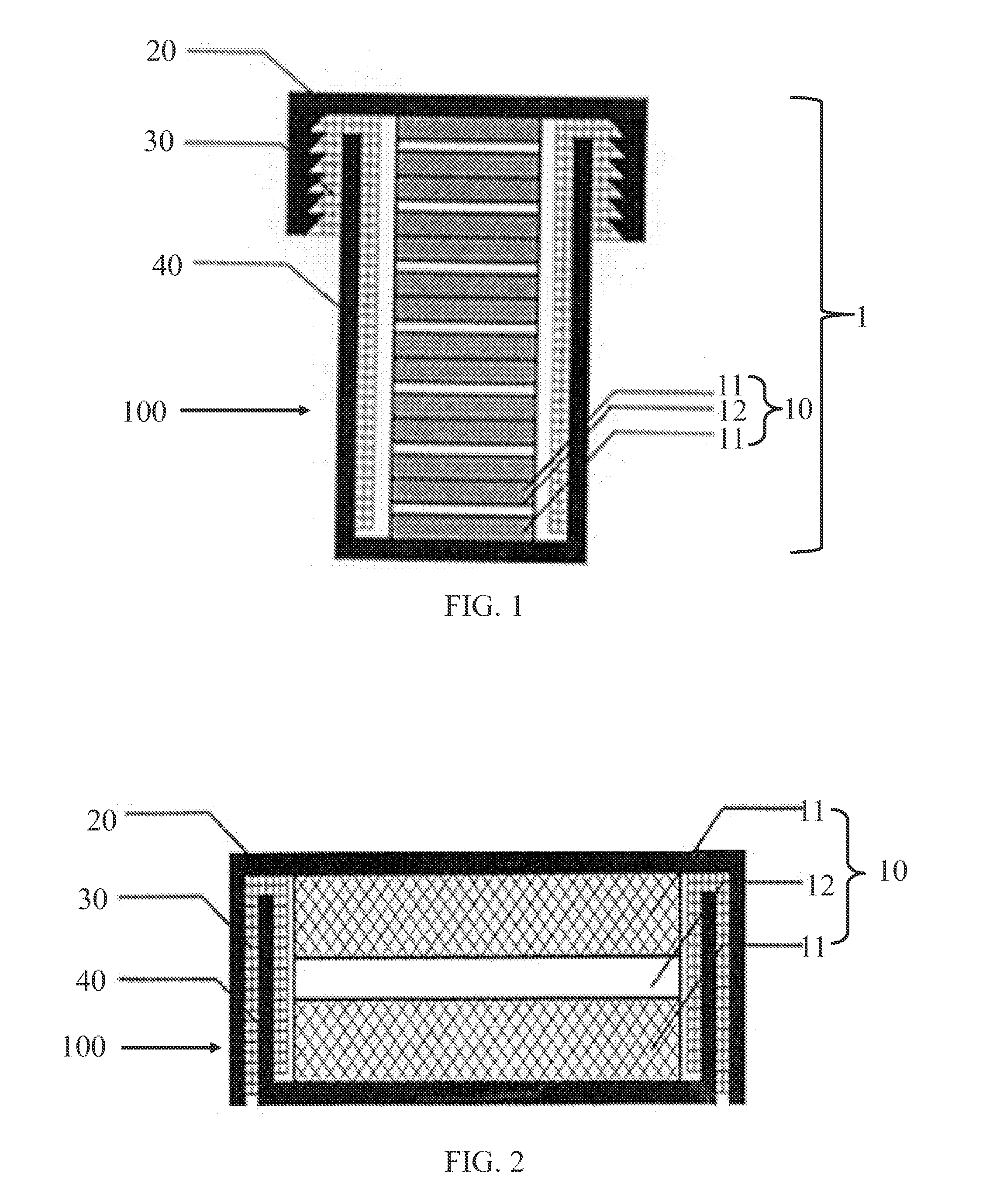
[0025]By material innovation and structural design of two modified carbonaceous electrodes and solid-state polymer electrolyte, it is easier to package the capacitor containing repeatedly stacked unit cells. The ways of packaging can be simplified, without drilling, welding, screwing with nails and making scaffolds which are common ways in the manufacture of a traditional capacitor module. The cost of manufacture can also be reduced. The thorough disclosure of the packaging structure is described in following embodiments.

[0026]One preferable embodiment

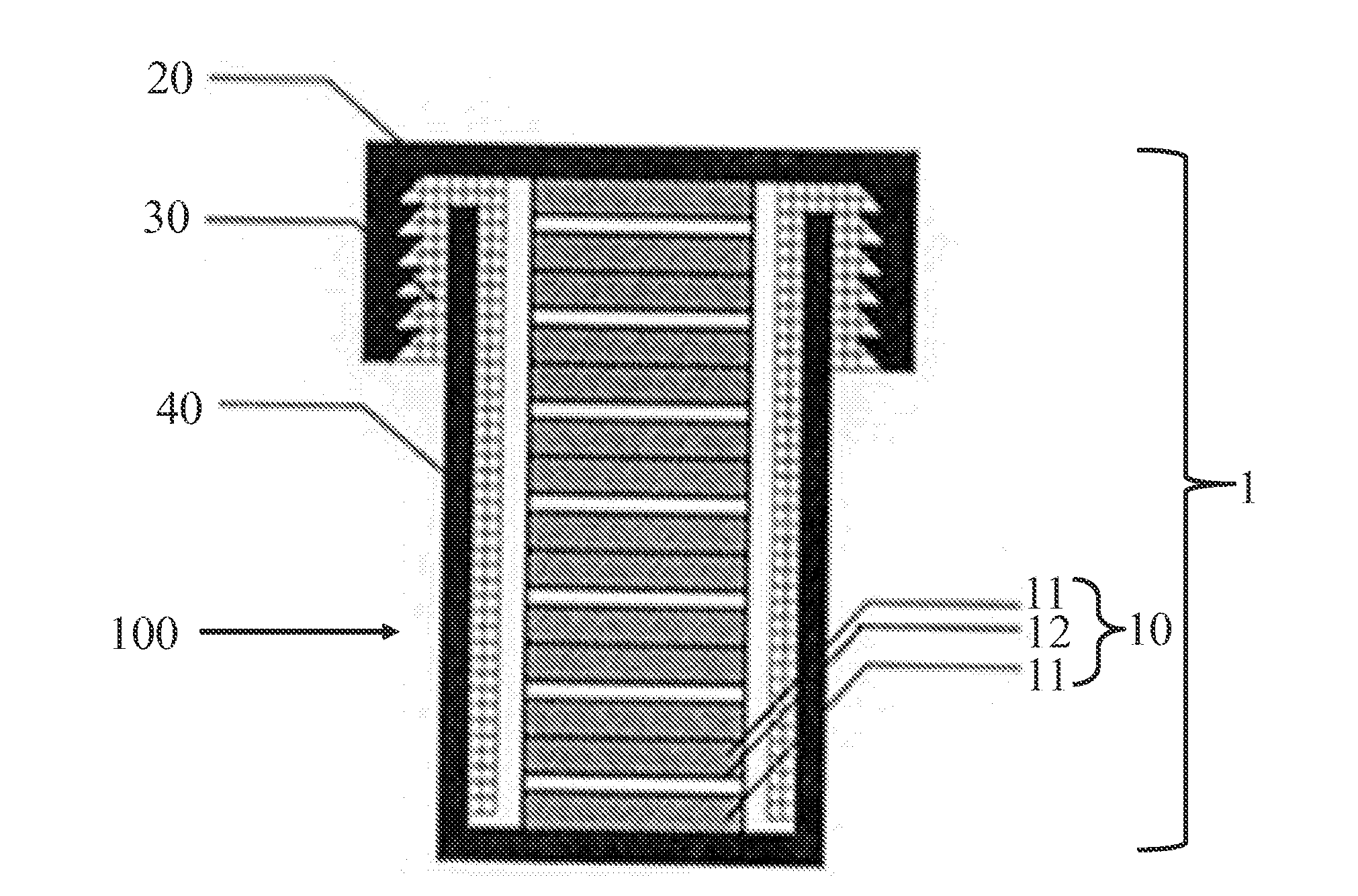
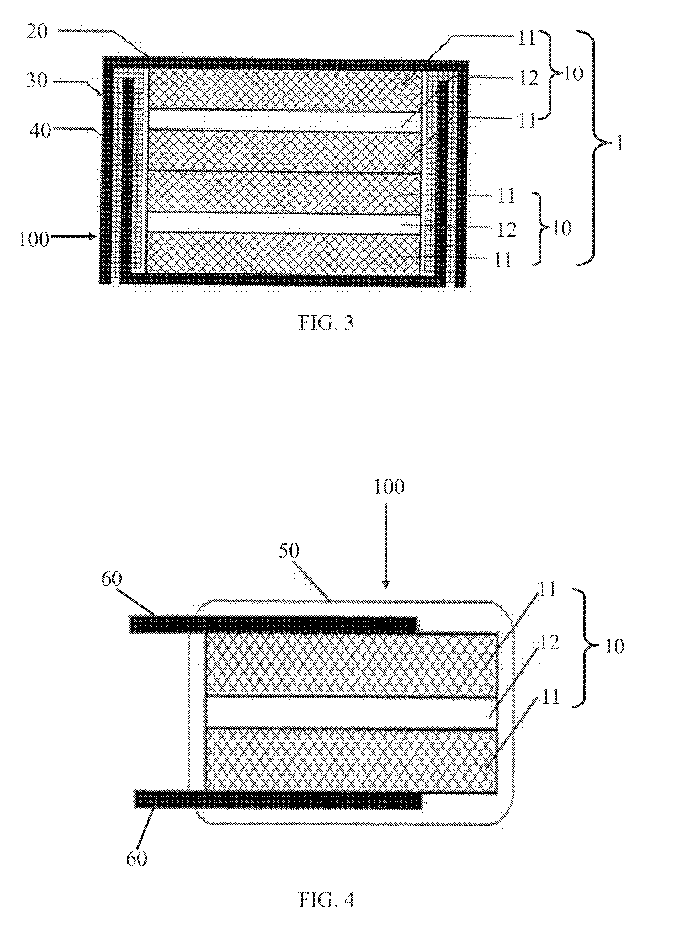
[0027]In FIG. 1, an energy storage device 100 comprises an upper metallic case 20, a lower metallic case 40, a sealing gasket 30 and an assembly of at least one unit cell of capacitor 1. The sealing gasket 30 is a polymer and is configured between the upper metallic case 20 and the lower metallic case 40. The assembly of at least one unit cell of capacitor 1 is configured in the lower metallic case 40 and comprises at least one unit ce...


PUM


Abstract

The invention relates to a packaging structure of an energy storage device. At least one unit cell of capacitor is stacked and packaged into the energy storage device. The unit cell is a sandwich structure comprising a solid-state polymer electrolyte between two modified carbonaceous electrodes. An assembly of at least one unit cell of capacitor can be packaged by metallic cases to form a coin cell type or screw type of the packaging structure, packaged with a plastic case by compression molding or injection molding, or packaged by a plastic bag or an aluminum-foil bag and sealed by heat sealing or vacuum heat sealing. Manufacture processes for traditional capacitor modules, such as drilling, welding, screwing, and making scaffolds, are not required. Although the packaging process is simpler and less expensive, the packaged energy storage device can perform better than traditional capacitor modules.

Description

BACKGROUND OF THE INVENTION[0001]1. Filed the Invention[0002]The present invention relates to packaging structures of an energy storage device, more particularly to at least one unit cell of capacitor by being repeatedly stacked and packaged to form the energy storage device.[0003]2. Description of Related Art[0004]A traditional capacitor comprises a pair of metallic collectors, a pair of electrodes, electrolyte, and a separator. The outer layer of the electrode is the metallic collector. The separator which is porous and the electrolyte are interposed between the two electrodes. In that the electrolyte is in the form of liquid or gel, a separator is needed to be interposed between the electrodes to prevent self-discharge and short circuit. The leakage of the electrolyte also needs to be prevented by polymeric sealing rings outside the pair of collectors. The packaging process can be completed by following steps of two leads penetrating a plastic case which may be made of polyvinylc...

Claims


Application Information

Patent Timeline
IPC IPC(8): H01G9/10H01G9/15
CPCH01G9/15H01G9/10H01G9/08
Inventor CHIU, KUO-FENGCHEN, SHI-KUNKO, TSE-HAO
Owner FENG CHIA UNIVERSITY
Learn More