Activation and Deactivation Assembly for an Electric Outboard Motor

a technology of electric outboard motors and assembly parts, which is applied in the direction of outboard propulsion units, marine propulsion, vessel construction, etc., can solve the problems of low efficiency, low efficiency, and failure point of leakage around the housing

Inactive Publication Date: 2015-01-01
GREZ JOSEPH W
View PDF5 Cites 7 Cited by
  • Summary
  • Abstract
  • Description
  • Claims
  • Application Information

AI Technical Summary

Benefits of technology

[0035]FIG. 14 is a perspective view of the fixed block member used to prevent rearward rotation of the motor step when the motor is reversed.

Problems solved by technology

While such propellers are relatively small and inefficient at speeds under 10 mph, the higher RPM and torque requirements of large propellers make them unsuitable for direct drive electric motors.
In addition, because the drive motor units are submerged, leaks around the housing is a failure point.
One drawback with watertight, sealed gear systems is that the gears and bearings must periodically cleaned and re-greased.
Another drawback is that the watertight, sealed system is that the watertight housing can fail allowing water or moisture to enter and damage the gears and bearings.
One drawback with non-watertight gear systems is that water has lower lubricating properties than grease making the gears and bearings vulnerable to greater wear and corrosion.
As a result, the gears and bearings used in non-watertight gear systems must be replaced more often which heretofore has been more expensive and time consuming than lubricating the gears and bearings in watertight, sealed systems.
As a result, the motor's lower shaft and propeller often contact submerged objects or the ground.
Unfortunately, not all small boats have battery straps or buckles or surfaces for affixing a battery.
In addition to holding the battery in a fixed location inside the boat, attaching the batteries to the boat is especially important because small boats can easily overturn in the water causing all non-buoyant objects, such as an electric batteries to be lost.

Method used


Image

  • Activation and Deactivation Assembly for an Electric Outboard Motor
  • Activation and Deactivation Assembly for an Electric Outboard Motor
  • Activation and Deactivation Assembly for an Electric Outboard Motor

Examples


Embodiment Construction

)

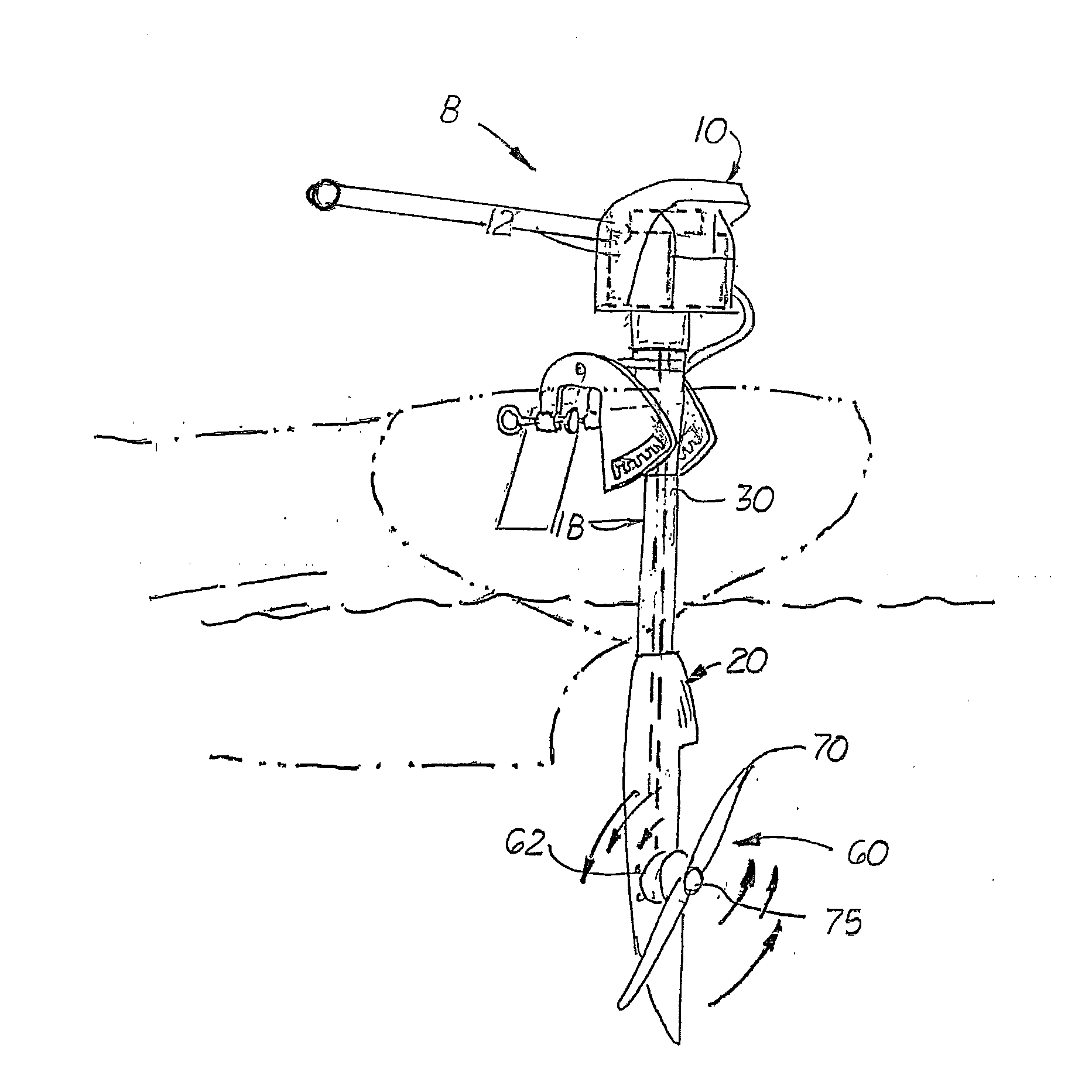
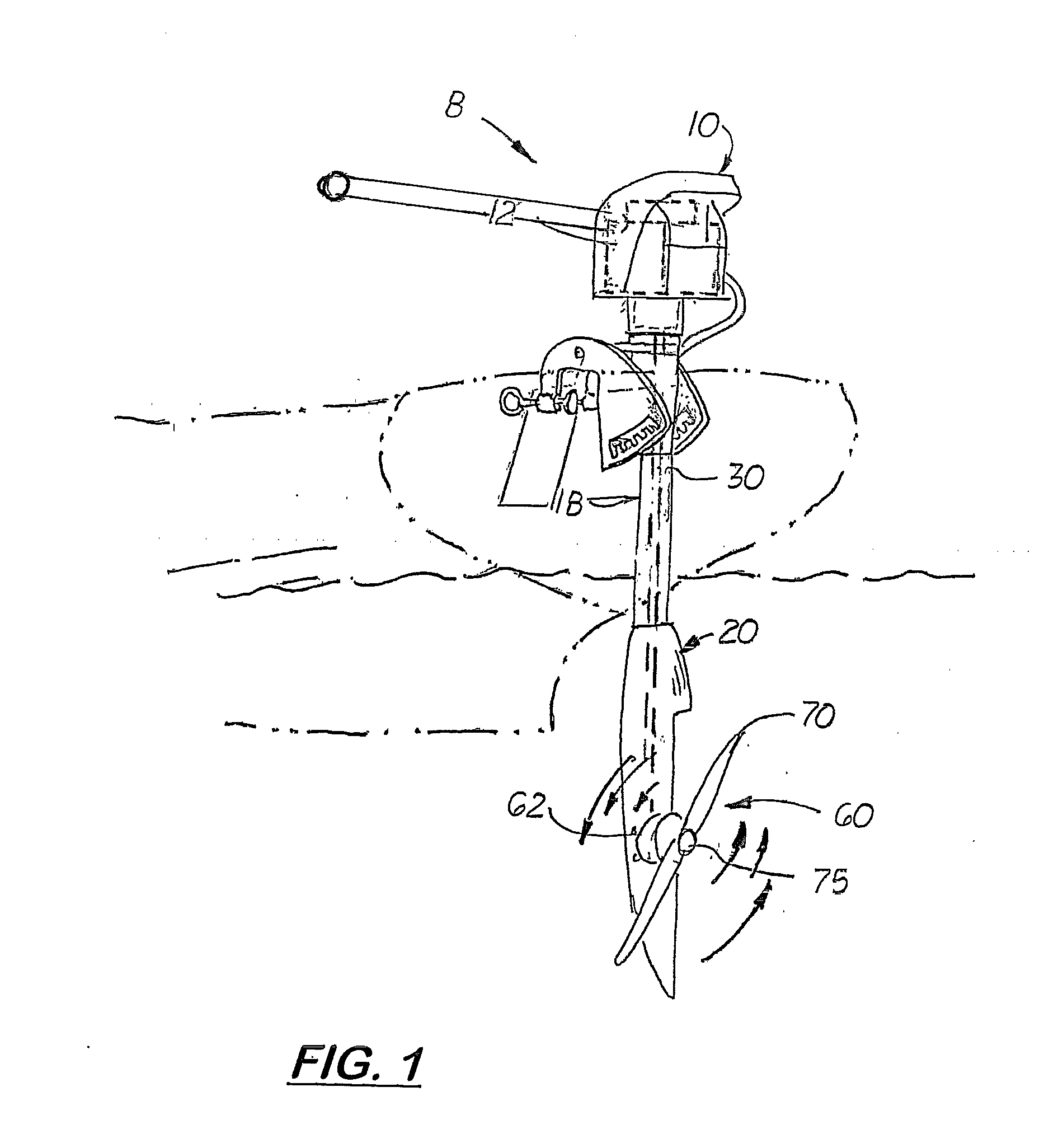
[0041]Referring to the accompanying Figs. there is shown an outboard electric motor assembly generally indicated by the reference number 8. The electric motor assembly 8 includes an electric motor 12 located in an upper housing 10. Attach and extending downward from the upper housing is a lower stem tube 18. Attached or integrally formed on the lower end of the lower stem tube 18 is a lower housing unit 20.

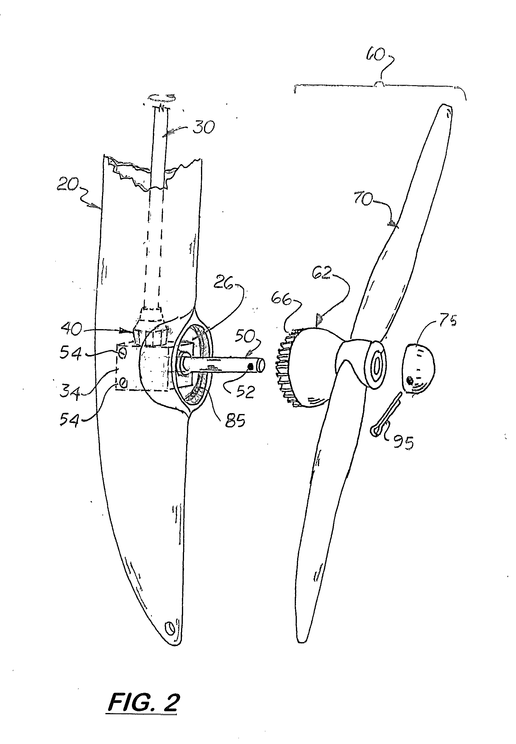
[0042]As shown in FIGS. 2 and 3, formed on the lower housing unit 20 is a receiving cavity 24 with a rearward facing circular opening 26. A drive shaft 30 is coupled at one end to the electric motor and extends downward through the lower stem tube 18 and into the receiving cavity 24. Located inside the receiving cavity 24 is a gear support block 34. The gear support block 34 is fixed inside the receiving cavity 24 and includes an upper bore 36 with a bearing 38 located therein. The distal end of the drive shaft 30 is connected to the bearing 38 thereby enabling it to rotate freel...


PUM


Abstract

An activation and deactivation assembly for an electric outboard motor with an internal motor controller, a tiller arm, a handle mounted on the tiller arm, and a rotating knob attached to the distal end of the handle. The knob has a longitudinally aligned key slot that receives a complimentary shaped key. Located inside the handle is a reed switch and mounted on the key is a magnet that is magnetically attracted to the reed switch. An optional lanyard attaches the key to the tiller arm, an optional dead main lanyard is attached to the lanyard, and a linear hall effect sensor is located in the handle.

Description

[0001]This is a divisional patent application based on U.S. Utility patent application 13 / 230,810 filed on Sep. 12, 2011 which is based on and claims the filing date benefit of U.S. provisional patent application (Application No. 61 / 381,490) filed on Sep. 10, 2010.COPYRIGHT NOTICE[0002]Notice is hereby given that the following patent document contains original material which is subject to copyright protection. The copyright owner has no objection to the facsimile or digital download reproduction of all or part of the patent document, but otherwise reserves all copyrights whatsoever.BACKGROUND OF THE INVENTION[0003]1. Field of the Invention[0004]This invention relates to outboard electric motors for boats, and more particularly to such outboard electric motors that are lightweight, portable and require little or no maintenance. maintenance.[0005]2. Description of the Related Art[0006]Operators of oar driven small boats, such as dinghies, canoes, kayaks and inflatable watercraft, find...

Claims


Application Information

Patent Timeline
Patent Type & Authority Applications(United States)
IPC IPC(8): B63H20/00
CPCB63H20/00B63H20/08B63H20/14B63H20/007B63H20/10B63H20/36
Inventor GREZ, JOSEPH, W.
Owner GREZ JOSEPH W
Why Eureka
Try Eureka