Self-expanding, balloon expandable stent-grafts

Active Publication Date: 2015-01-01
WL GORE & ASSOC INC
View PDF13 Cites 20 Cited by
  • Summary
  • Abstract
  • Description
  • Claims
  • Application Information

AI Technical Summary

Benefits of technology

The patent describes a way to make grafts that can be customized to fit different sizes of vessels. This improves the ability to treat diseased vessels and reduces the risk of complications from grafts that are too big. The technique can be used for a range of applications, such as stent-grafts for peripheral arcs and aneurysm repair. The use of a fracturable coating also minimizes the risk of complications from the stent-graft against the vessel wall.

Problems solved by technology

Some degree of impregnation may occur with coatings that are applied to the substrate surfaces.

Method used


Image

  • Self-expanding, balloon expandable stent-grafts
  • Self-expanding, balloon expandable stent-grafts
  • Self-expanding, balloon expandable stent-grafts

Examples


example 1

Diametrically Adjustable Vascular Graft

[0055]The following is a description of a method used to make a diametrically extensible vascular graft that may be increased in diameter by inflation of a catheter balloon placed temporarily within the lumen of the vascular graft. The method described for making of the balloon extensible vascular graft is similar to a method described below for making of a balloon extensible stent-graft. The example of the vascular graft described herein was made to be diametrically extensible from a 4 mm inside diameter to a 6 mm inside diameter; larger ranges of extensibility are possible. A flow chart summary of this manufacturing process is described by FIG. 11.

[0056]First, a longitudinally extruded and expanded ePTFE tube was obtained, the tube having a 6 mm inside diameter, 15 cm length, 0.6 mm wall thickness and approximate 22 micron mean fibril length. This tube was fitted over a 6 mm outside diameter (OD) stainless steel mandrel. The tube was then pro...

example 2

Self Expanding / Balloon Adjustable Stent-Graft

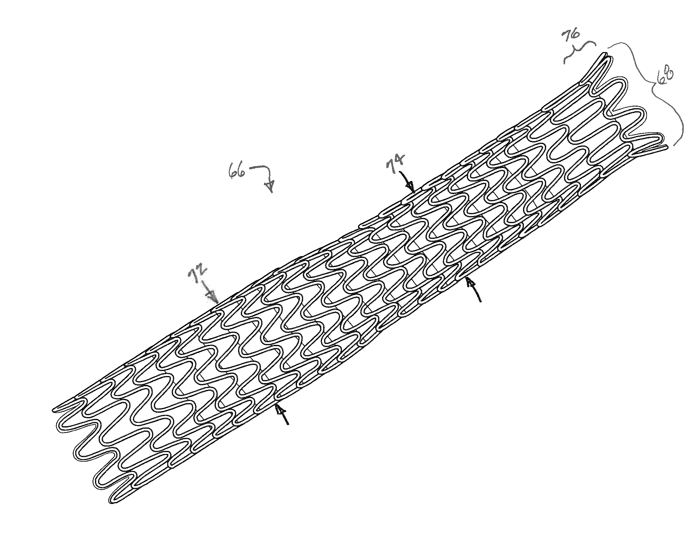
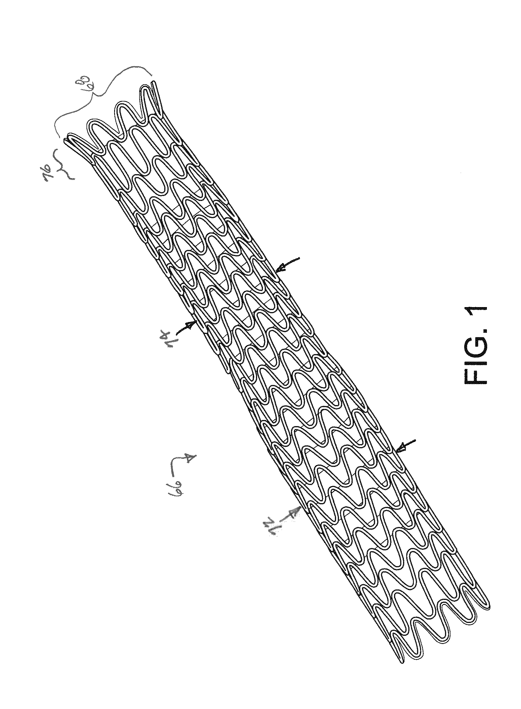
[0063]A 4 mm covered stent-graft with a self-expanding nitinol wire stent (a helically wound serpentine wire form) that can be subsequently extended in diameter (e.g., with a catheter balloon) to 6 mm was made as described below; this stent-graft is illustrated in FIG. 1 which shows a portion of the stent-graft having been balloon expanded to an ID of 6 mm.

[0064]An ePTFE tube was obtained, the tube having a 6 mm ID, about 8 cm length, bulk density of about 0.6 g / cc, 0.1 mm wall thickness and approximate 22 micron mean fibril length. This tube was fitted over a 6 mm OD stainless steel mandrel, then wrapped with FEP-coated ePTFE film and heated as described above for the example of the diametrically extensible vascular graft. The graft was then removed from the 6 mm OD stainless steel mandrel. An ePTFE sacrificial cushion tube as described previously was fitted onto a 6 mm OD porous stainless steel mandrel, after which the film-wrapped ePTF...

example 3

Length Adjustable Vascular Graft

[0075]A length adjustable 6 mm vascular graft was produced by making an about 25 cm long vascular graft in the method described above for the diametrically extensible graft. The graft was then placed on a 6 mm stainless steel mandrel, and then compressed longitudinally to a length of about 7.5 cm, or about 30% of its original length. In the process, the fibrils in the graft including the fibrils of the film become bent. The graft on the mandrel was placed in a 320° C. convection oven for 10 minutes. During this process the FEP on the film of the graft was melted and flows into the void spaces between the bent fibrils. After removal from the oven and cooling to about ambient temperature, the graft was removed from the mandrel. The length of the graft thus shortened was about 50% less than the original length. The FEP mingled with the bent fibrils retains the graft in its shortened length until it was manually extended by the application of a tensile fo...


PUM

PropertyMeasurementUnit
Diameteraaaaaaaaaa
Expansion enthalpyaaaaaaaaaa

Abstract

A stent-graft having a smaller compacted diameter suitable to allow the stent-graft to be transported through a body conduit to a desired site. The stent-graft is deployed at the desired site by self-expanding to a first larger diameter from the smaller compacted diameter. The stent-graft has at least one flared end when self-expanded to the first larger diameter. The stent graft is further diametrically expandable by the application of force such as the inflation of a catheter balloon within the stent-graft to a still larger, maximum second diameter that is equal to about the maximum diameter of the flared end.

Description

FIELD OF THE INVENTION[0001]The present invention relates to the field of self-expandable stent-grafts that are further additionally balloon expandable.BACKGROUND OF THE INVENTION[0002]Various commercial articles have been manufactured from porous materials having fibrillar microstructures including various implantable medical devices. Examples of these materials may include porous expanded polytetrafluoroethylene (ePTFE) and stretched polyethylenes and polypropylenes. Articles fabricated from these porous fibrillated materials include fabrics, battery membranes, various filters, electrical insulation and various medical devices including vascular grafts, tissue repair patches, sutures and stent-grafts. Porous materials used to manufacture articles such as these can take the form of, for example, sheets, thin films and tubes. It is known that nominal physical dimensions of some of these articles may be changed (reduced) by applying compressive forces to these materials, particularly...

Claims


Application Information

Patent Timeline
IPC IPC(8): A61F2/07A61F2/92
CPCA61F2/92A61F2/07A61L31/048A61L31/022A61F2/82A61F2/89A61L27/507A61L27/16A61L27/50A61L31/14A61L27/34A61L31/10C08L27/18
Inventor KOVACH, LARRY J.UERLING, RAYMOND W.
Owner WL GORE & ASSOC INC
Why Eureka
Try Eureka