Thermal Imaging Sensors

Inactive Publication Date: 2015-01-08
PST SENSORS
View PDF15 Cites 4 Cited by
  • Summary
  • Abstract
  • Description
  • Claims
  • Application Information

AI Technical Summary

Benefits of technology

The patent text describes a sensor device that has an array of small sensors placed on a flexible or conformable blanket. Each sensor has a unique design and can measure different physical variables, such as temperature or strain, independently. The sensors are connected in different configurations, and can be customized to match the shape and size of the object they are measuring. The sensor elements may also be printed onto the substrate. The technical effect of this invention is the creation of a flexible and customizable sensor array that can measure different physical variables with high accuracy and precision.

Problems solved by technology

While having the advantage, for some applications, of being a non-contact measurement, this is often a disadvantage due to factors such as extraneous radiation, poor visibility and obscuring of the field of view, transparency of the material and variations in emissivity and reflectivity.
The construction, and equally important, the electrical connection of a flexible multi-sensor array can be complex and expensive, as in the device described in U.S. Pat. No. 6,077,228 of Schonberger, for example.

Method used


Image

  • Thermal Imaging Sensors
  • Thermal Imaging Sensors
  • Thermal Imaging Sensors

Examples


Embodiment Construction

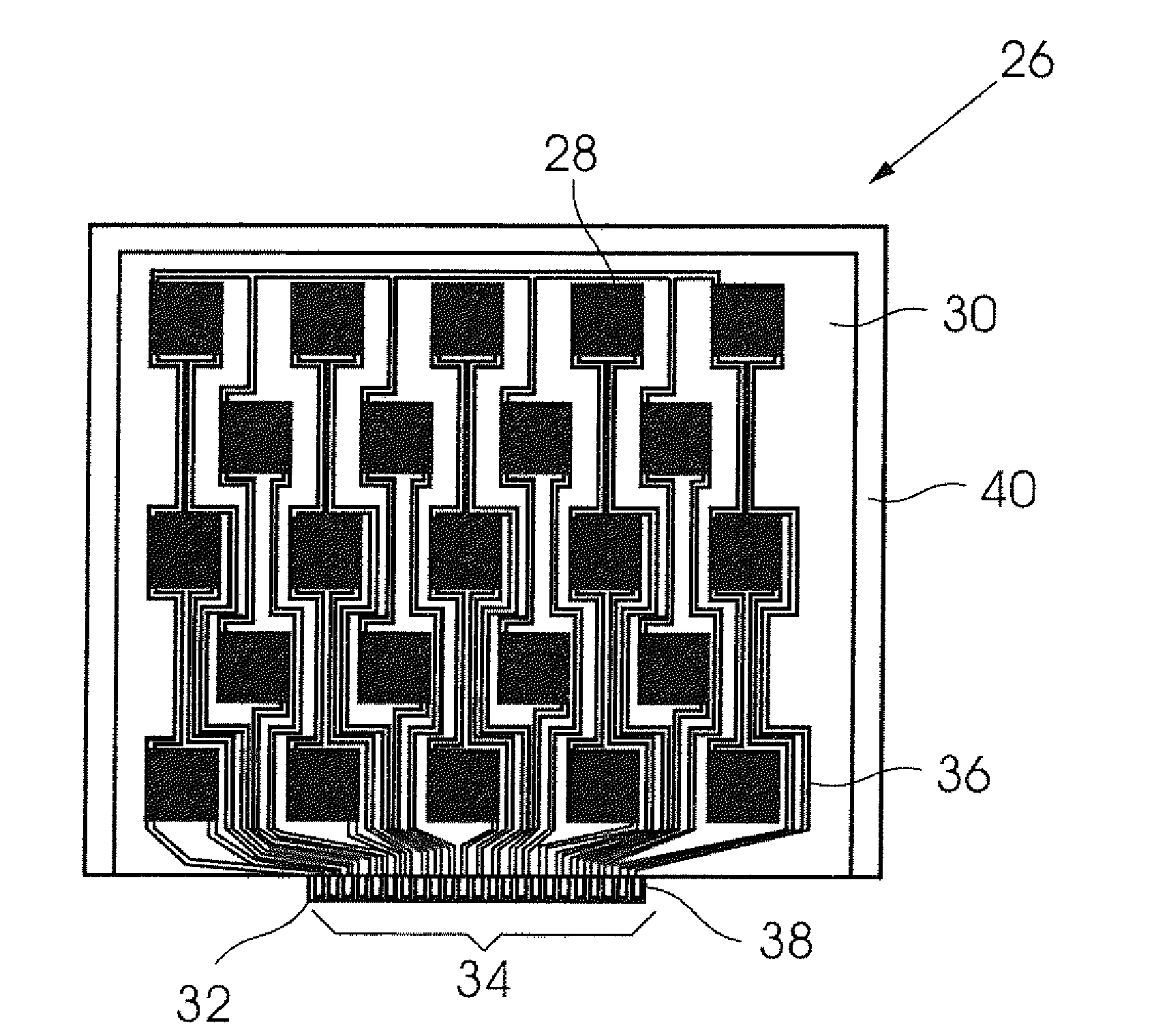
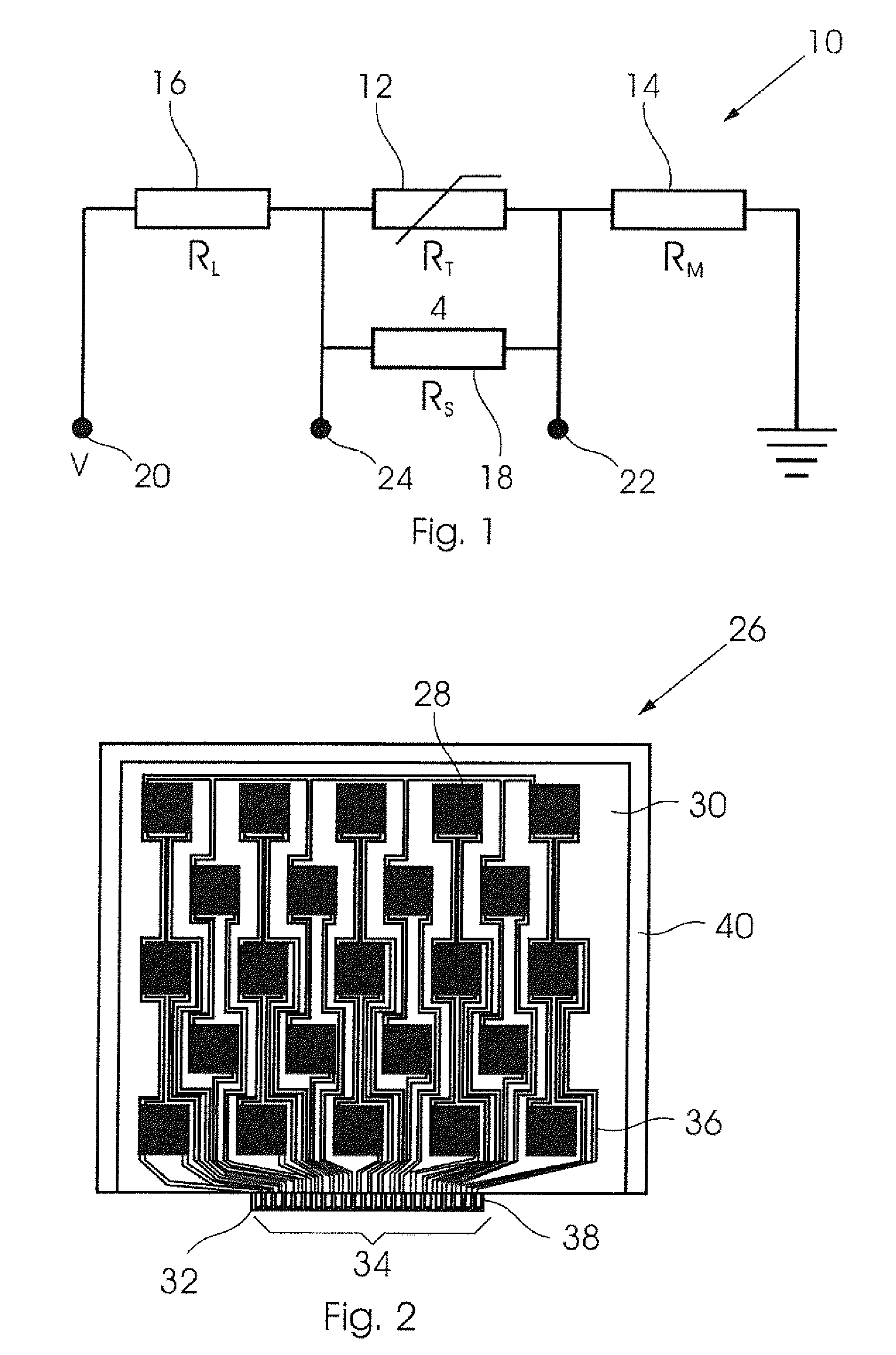
[0026]For purposes of explanation, the present invention will be described primarily with reference to temperature sensing devices. However, it will be understood that sensing devices for strain or pressure, or optical sensing devices, for example, are other examples of the invention.

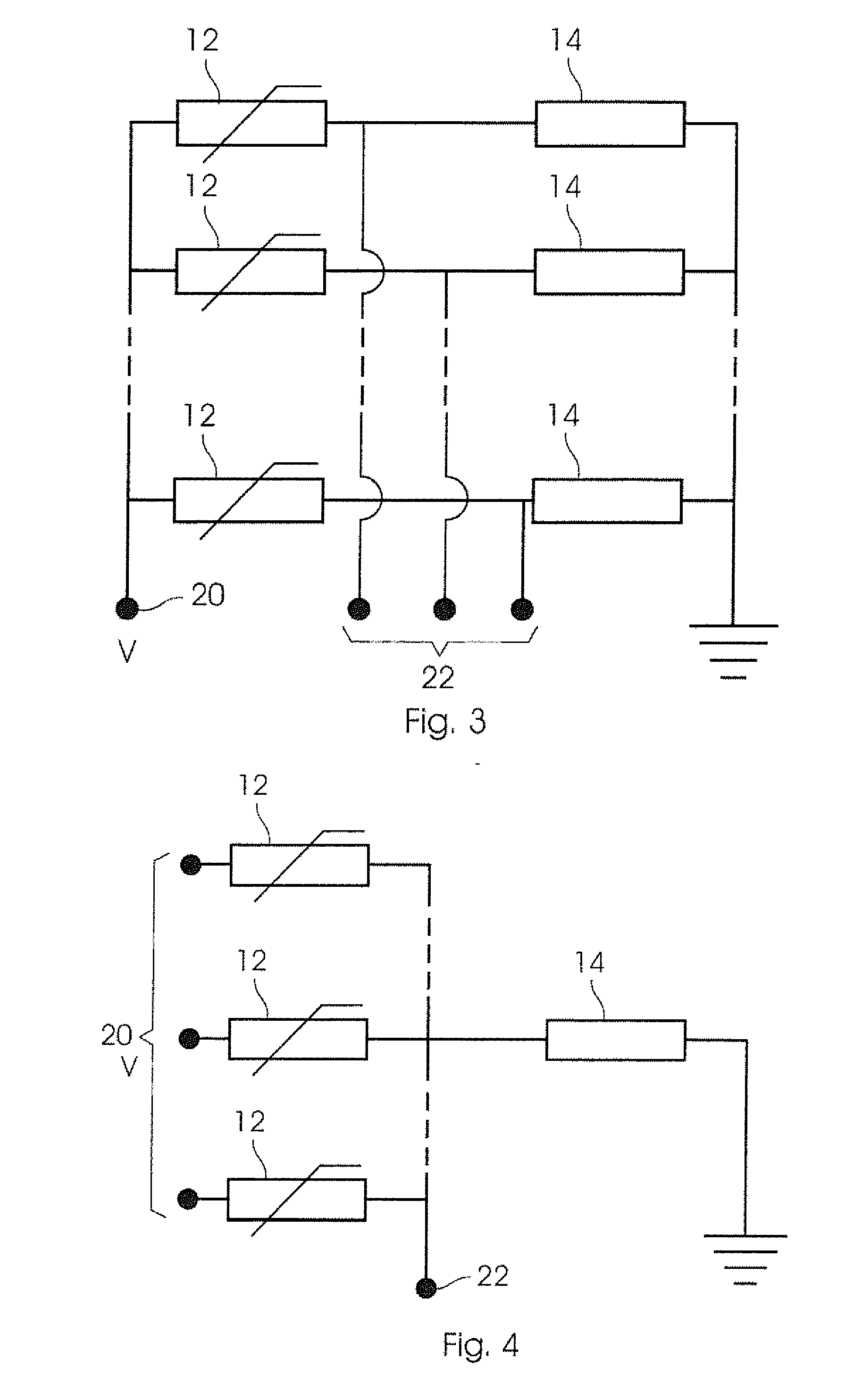
[0027]The temperature sensing devices of the invention described herein are relatively large area thermal imaging sensors composed of a network of temperature dependent resistors, commonly known as thermistors, and temperature independent fixed resistors. Of particular relevance here are thermistors which have a negative temperature coefficient of resistance, commonly known as NTC thermistors, meaning that their electrical resistance decreases approximately exponentially with increasing temperature.

[0028]Thus, one aspect of the present invention provides a plurality of thermistors which are arranged in a temperature sensing array, where the sensors may be individually addressed or addressed as a row and...


PUM


Abstract

A sensor device comprises an array of spaced apart sensor elements disposed in a pattern on a substrate. Each sensor element is connected electrically so that a physical variable measured by each sensor element independently can be recorded and / or displayed by an external instrument. The sensing device may be a temperature sensing device, in which case the sensor elements are temperature sensing elements such as negative temperature coefficient (NTC) thermistors. Alternatively the sensing device may be a strain or pressure sensing device, or an optical imaging device, in which case the sensor elements include piezoresistors or photoresistors. The sensor elements may be connected in a common source or write all—read one configuration, in a common output or write one—read all configuration, or in an array comprising X rows and Y columns, in a write X—read Y configuration,

Description

BACKGROUND OF THE INVENTION[0001]THIS invention relates to sensor devices such as temperature sensing devices, and to a method of producing such devices.[0002]In many applications, in fields as diverse as engineering, health care, packaging and transport it is desirable to obtain quantitative information on the distribution of the temperature of a relatively large object (for example, a container for liquid or a package containing foodstuffs).[0003]At present the most common method used for this purpose is infrared or visible thermography, in which the thermal radiation emitted by the object is recorded by a digital camera. While having the advantage, for some applications, of being a non-contact measurement, this is often a disadvantage due to factors such as extraneous radiation, poor visibility and obscuring of the field of view, transparency of the material and variations in emissivity and reflectivity. It is therefore often desirable to utilize a sensor which is in good direct ...

Claims


Application Information

Patent Timeline
IPC IPC(8): G01K7/22G01J1/44G01L1/18
CPCG01K7/22G01K2213/00G01J1/44G01L1/18G01K7/16G01K1/02G01L9/045G01L1/205G01L1/225
Inventor BRITTON, DAVID THOMASHARTING, MARGIT
Owner PST SENSORS
Why Eureka
Try Eureka