Temperature control device of an optical semiconductor device

a technology of temperature control device and optical semiconductor, which is applied in the direction of heat measurement, instruments, domestic cooling apparatus, etc., can solve problems such as temperature differences

Inactive Publication Date: 2000-01-11
YOKOGAWA ELECTRIC CORP
View PDF6 Cites 74 Cited by
  • Summary
  • Abstract
  • Description
  • Claims
  • Application Information

AI Technical Summary

Benefits of technology

It is therefore an object of the present invention to provide a temperature control device of an optical semiconductor device capable of keeping the temperature of an optical semiconductor device constant even if a part of the thermal conductor is suscept

Problems solved by technology

However the conventional temperature control device of an optical semiconductor device has a problem in that since the temperature detecting point 12 is spaced apart from the optical semiconductor

Method used


Image

  • Temperature control device of an optical semiconductor device
  • Temperature control device of an optical semiconductor device
  • Temperature control device of an optical semiconductor device

Examples


Embodiment Construction

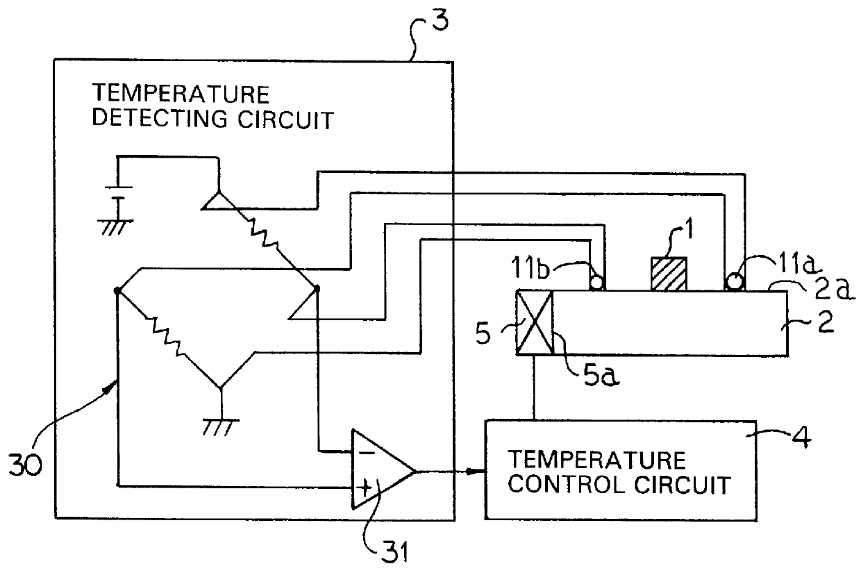
A temperature control device of an optical semiconductor device of the present invention will be now described with reference to FIG. 1 which is a block diagram showing a structure of the temperature control device of an optical semiconductor device according to the preferred embodiment of the invention.

An optical semiconductor device 1 comprises a laser diode, an LED, a photodiode, etc. A thermal conductor 2 comprises a block made of a material having an excellent conductivity such as copper, iron. The optical semiconductor device 1 is fixed to a surface 2a of the thermal conductor 2, and a Peltier element 5 is jointed to a jointing surface 5a of the thermal conductor 2 at one side surface thereof.

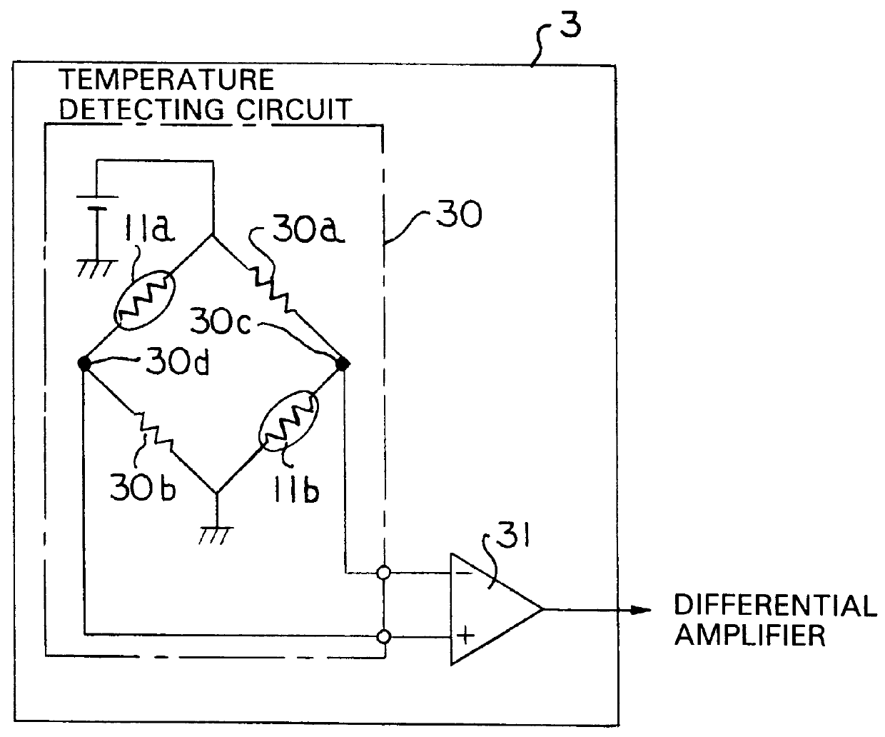
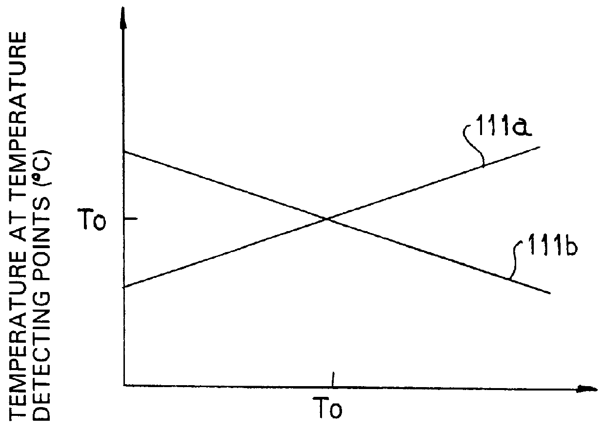
Thermistors 11a and 11b are respectively attached to the surface 2a of the thermal conductor 2 where they are susceptible stronger and weaker to an ambient temperature rather than the optical semiconductor device 1 is susceptible to the ambient temperature. That is, the temperature contro...


PUM


Abstract

A temperature control device of an optical semiconductor device is provided for keeping the optical semiconductor device constant. An optical semiconductor device is fixed to a thermal conductor. One thermistor is arranged on the thermal conductor at the portion where it is susceptible stronger to an ambient temperature rather than the optical semiconductor device is susceptible to the ambient temperature while another thermistor is arranged on the thermal conductor at the portion where it is susceptible weaker to the ambient temperature rather than the optical semiconductor device is susceptible to the ambient temperature. The difference between an average temperature of the thermal conductor at two points detected by the thermistors and a set temperature is detected by a temperature detecting means comprising a bridge circuit having the thermistors which are connected to each other so as to form opposing sides of the bridge circuit and a differential amplifier for receiving an imbalanced voltage of the bridge circuit. The thus detected difference of the temperature is outputted to a temperature control circuit, whereby the temperature control circuit controls a Peltier driving current of a Peltier element so that the average temperature of the thermal conductor at two points thereof and the set temperature become equal to each other.

Description

BACKGROUND OF THE INVENTION1. Field of the InventionThe present invention relates to a temperature control device of an optical semiconductor device needing an environment which is less changed in temperature, particularly to that having temperature detecting points where the optical semiconductor device is clamped at both sides, in which one is susceptible to an ambient temperature and the other is not susceptible to the ambient temperature rather than the optical semiconductor device to the ambient temperature, and wherein an average temperature at both temperature detecting points is constant, thereby controlling the temperature of the optical semiconductor device.2. Prior ArtA conventional temperature control device of an optical semiconductor device of this type is used for permitting the temperature of optical semiconductor device, etc. to keep constant. FIG. 4 is a block diagram showing one example of a construction of the conventional temperature control device of an optical...

Claims


Application Information

Patent Timeline
IPC IPC(8): G05D23/20G05D23/24G05D23/00G01K7/24
CPCG05D23/24G05D23/1931
Inventor EMA, TAKAYUKI
Owner YOKOGAWA ELECTRIC CORP
Why Eureka
Try Eureka