Device for heat treatment

a heat treatment and device technology, applied in the field of devices for heat treatment, can solve the problems of limiting the cleanliness conditions inside the process space, affecting the service life of the furnace, and consuming a lot of energy, and achieves the effects of rapid heating and cooling of the material to be heated, variable shape, and easy manufacturing

Inactive Publication Date: 2015-01-08
HERAEUS NOBLELIGHT GMBH
View PDF3 Cites 3 Cited by
  • Summary
  • Abstract
  • Description
  • Claims
  • Application Information

AI Technical Summary

Benefits of technology

[0011]The invention is based on the object to provide a device for heat treatment that has a furnace lining that can be manufactured easily and in variable shape and enables rapid heating and cooling of the material to be heated and short process times, and is characterised by a long service life.General Description of the Invention

Problems solved by technology

The infrared radiators are often arranged inside the process space and are thus exposed to high temperatures which causes their service life to be limited.
Since the furnace lining needs to be heated first after the furnace is switched on, the high heat capacity of the lining causes the furnace to take relatively long to heat up and to also have a high energy consumption.
The use of furnace linings made of fireclay also limits the cleanliness conditions inside the process space.
Furnaces having a furnace lining made of fireclay are characterised by their high weight and they are therefore available for mobile use only to a limited degree.
However, the heating time and the cooling time are prolonged by the furnace lining in this furnace as well.
Moreover, furnaces with a furnace lining made of fireclay have a low heat shock resistance such that cracks in the furnace lining may arise if the furnace is opened before time.

Method used


Image

  • Device for heat treatment
  • Device for heat treatment
  • Device for heat treatment

Examples


example 1

[0060]In the first embodiment, the device for heat treatment (not shown) comprises a furnace lining in the form of a cuboidal hollow body; the furnace lining comprises multiple wall elements 1 made of quartz glass, a floor plate, and a cover plate.

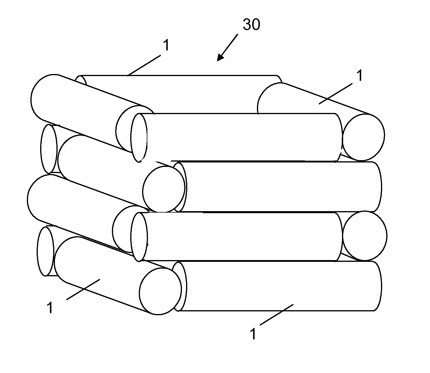
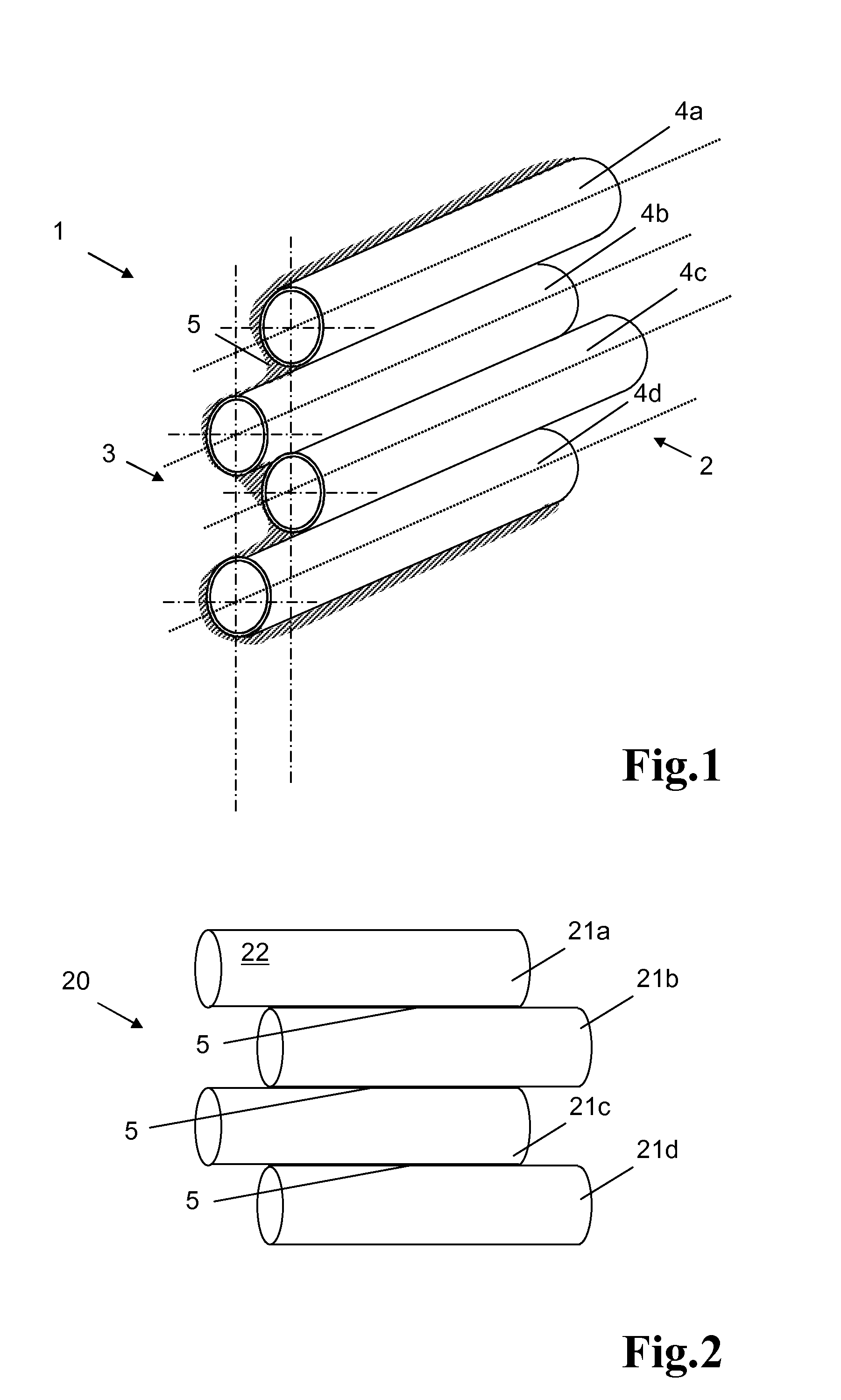
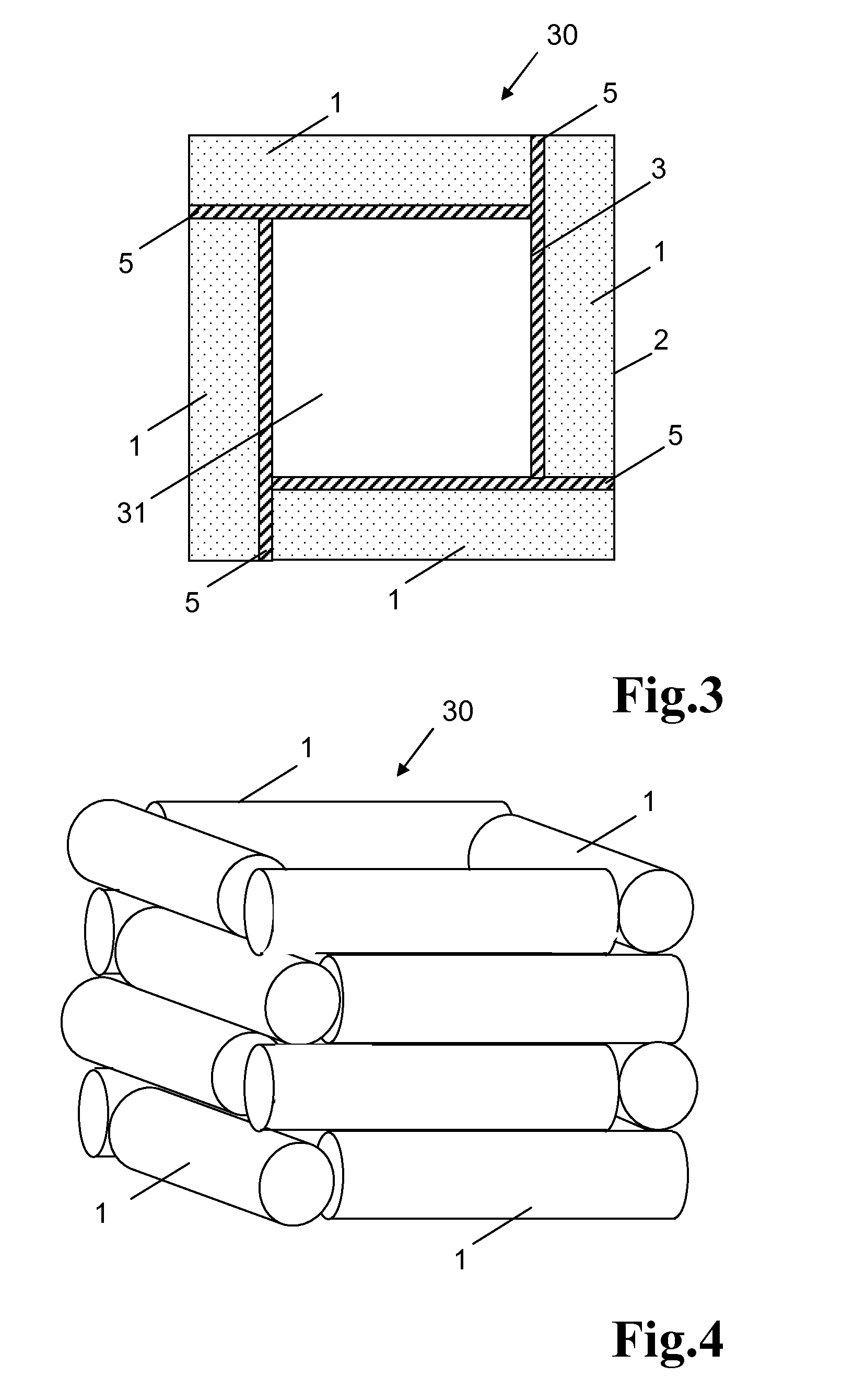
[0061]FIG. 3 shows a top view of four wall elements 1 that are stood up vertically and are connected to each other by means of a joined connection. The composite, in toto, has reference number 30 assigned to it. The wall elements 1 are assembled appropriately such that the ends of the wall elements 1, which are alternately offset by 50 mm with respect to each other, are nested inside each other and are connected to each other in a log house design. Each wall element 1 comprise a side 2 facing away from the process space 31 and a side 3 facing the process space 31. The side 3 facing the process space 31 is coated with the SiO2-containing connecting mass 5. A spatial view of the wall elements 1 connected in a log house design is shown in FIG...

example 2

[0074]The design of the device differs from the design of the device from exemplary embodiment 1 in that it eliminates two wall elements 1 situated opposite from each other. The openings are preparations for continuous introduction of the material to be heated. The furnace having the novel internal lining, in the form of the remaining two walls with cover and floor, is loaded in the middle in warm and switched-on condition (electrical power kept at 1.5 kW). The goods holder is situated at a distance of 60 mm from the heating field (floor).

[0075]The sample made of quartz glass, as described in exemplary embodiment 1, is heated up from room temperature, initially at a gradient of approx. 9 K / min, and reaches the temperature of 600° C. after only three minutes and a maximal temperature of 740° C. after 14 minutes. The difference to the maximal temperature of 800° C. as in example 1 is related to convective losses due to the two side openings and the somewhat larger distance between the...

example 3

[0076]The design of the furnace according to example 3 corresponds to that of the device from example 2. The furnace is operated in warm and switched-on condition (permanent electrical power of 1.5 kW) and used for a continuous sintering process. For this purpose, a component coated on the upper side with gold, for example a quartz glass tube having dimensions of L×W×H=1,000×34×14 mm, is guided appropriately through the furnace to burn-in the coating such that the component moves through the hot process chamber of the furnace at a speed of 200 mm / min and is guided out on the opposite side. The component is moved through the furnace using a holder situated outside the furnace. The tube is moved keeping a distance of 60 mm to the heating field of the floor plate.

[0077]Downstream of the furnace, the coating on the tube has a visually homogeneous surface with very good surface adhesion. The adhesion of the gold to the surface was determined using the adhesive tape tear-off test. Said te...


PUM

PropertyMeasurementUnit
outer diameteraaaaaaaaaa
temperaturesaaaaaaaaaa
temperatureaaaaaaaaaa

Abstract

Known devices for heat treatment comprise a process space surrounded by a furnace lining made of quartz glass, a heating facility, and a reflector. In order to provide, on this basis, a device for heat treatment having a furnace lining that can be manufactured easily and in variable shapes and enables rapid heating and cooling of the material to be heated and short process times and is characterised by its long service life, the invention proposes that the furnace lining comprises multiple wall elements having a side facing the process space and a side facing away from the process space, and that at least one of the wall elements comprises multiple quartz glass tubes that are connected to each other by means of an SiO2-containing connecting mass.

Description

CROSS-REFERENCE TO RELATED APPLICATIONS[0001]This application is a Section 371 of International Application No. PCT / EP2013 / 000074, filed Jan. 12, 2013, which was published in the German language on Aug. 22, 2013, under International Publication No. WO 2013 / 120571 A1 and the disclosure of which is incorporated here-in by reference.BACKGROUND OF THE INVENTION[0002]The invention relates to a device for heat treatment comprising a process space surrounded by a furnace lining made of quartz glass, a heating facility, and a reflector.[0003]Devices of this type are well-suited, in particular, for heating substrates to temperatures above 600° C.PRIOR ART[0004]Industrial electrical heating furnaces used for heating a material to be heated to temperatures above 600° C. often use infrared radiators emitting short-wave, medium-wave and / or long-wave infrared radiation as heating elements. The infrared radiators are often arranged inside the process space and are thus exposed to high temperatures...

Claims


Application Information

Patent Timeline
Patent Type & Authority Applications(United States)
IPC IPC(8): F27D1/00H05B6/00H05B3/62
CPCF27D1/00H05B6/00H05B3/62F27D1/0006
Inventor WEBER, JURGENDIEHL, FRANKLINOW, SVEN
Owner HERAEUS NOBLELIGHT GMBH
Why Eureka
Try Eureka