Fuel cell system

a fuel cell and system technology, applied in the field of fuel cell systems, can solve the problems of difficult to keep the na-s battery in the operating state all the time, na-s battery may be overheated, sodium-sulfur heat shortage may occur, etc., to achieve effective heat utilization without excessive losses in electrical power, and suppress electrical power loss. , the effect of rapid fluctuation of electrical power

Active Publication Date: 2015-01-08
HONDA MOTOR CO LTD
View PDF11 Cites 7 Cited by
  • Summary
  • Abstract
  • Description
  • Claims
  • Application Information

AI Technical Summary

Benefits of technology

[0017]In the present invention, the air cooling condensing mechanism includes the secondary battery for inducing endothermic reaction during charging and inducing exothermic reaction during discharging. The temperature of the secondary battery is kept in a chargeable and dischargeable state using the exhaust gas as the heat medium during charging, and using the oxygen-containing gas as the coolant during discharging. In the system, by charging and discharging of the secondary battery, the electrical power outputted from the fuel cell system can be changed in accordance with the electrical power required for the load, and to follow rapid fluctuation of the electrical power required for the load easily.
[0018]Further, the exhaust gas is used during charging of the secondary battery, and the oxygen-containing gas is used during discharging of the secondary battery. Thus, it is possible to suppress losses of electrical power and achieve effective heat utilization without any excessive losses in the electrical power. Accordingly, improvement in the power generation efficiency and the heat efficiency, i.e., improvement in the overall efficiency is achieved.
[0019]Further, the temperature of the exhaust gas is decreased, and it becomes possible to condense the water vapor in the exhaust gas to collect the condensed water. Thus, generation of waste heat is suppressed, and water self-sustaining operation is facilitated. Further, since the temperature of the oxygen-containing gas is increased, thermally self-sustaining operation is facilitated easily.

Problems solved by technology

However, in the Na-S battery, since exothermic reaction occurs during discharging, the Na-S battery may be overheated.
Therefore, it may be difficult to keep the Na-S battery in the operating state all the time.
Further, in the conventional technique 2, during charging of the sodium-sulfur battery (endothermic reaction) when the heat demand is large, the exhaust heat from the fuel cell stack 2b is not sufficient, and heat shortage may occur in the sodium-sulfur battery 5b undesirably.
Further, during discharging of the sodium-sulfur battery 5b (exothermic reaction), there is no way to decrease the temperature of the sodium-sulfur battery.
Therefore, it may be difficult to keep the sodium-sulfur battery 5b in the operating state all the time.

Method used


Image

  • Fuel cell system
  • Fuel cell system
  • Fuel cell system

Examples


first embodiment

[0028]A fuel cell system 10 according to the present invention is used in various applications, including stationary and mobile applications. For example, the fuel cell system 10 is mounted in a vehicle.

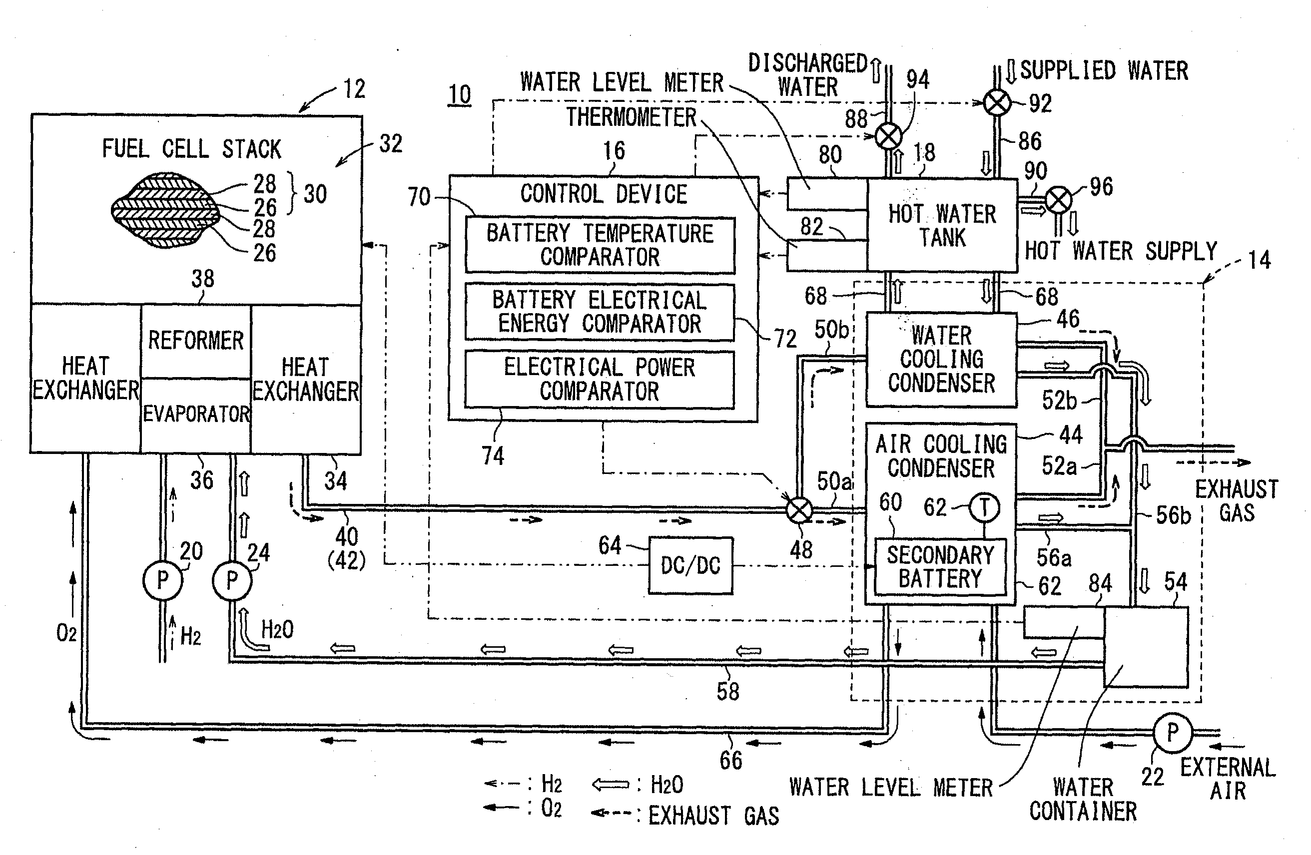
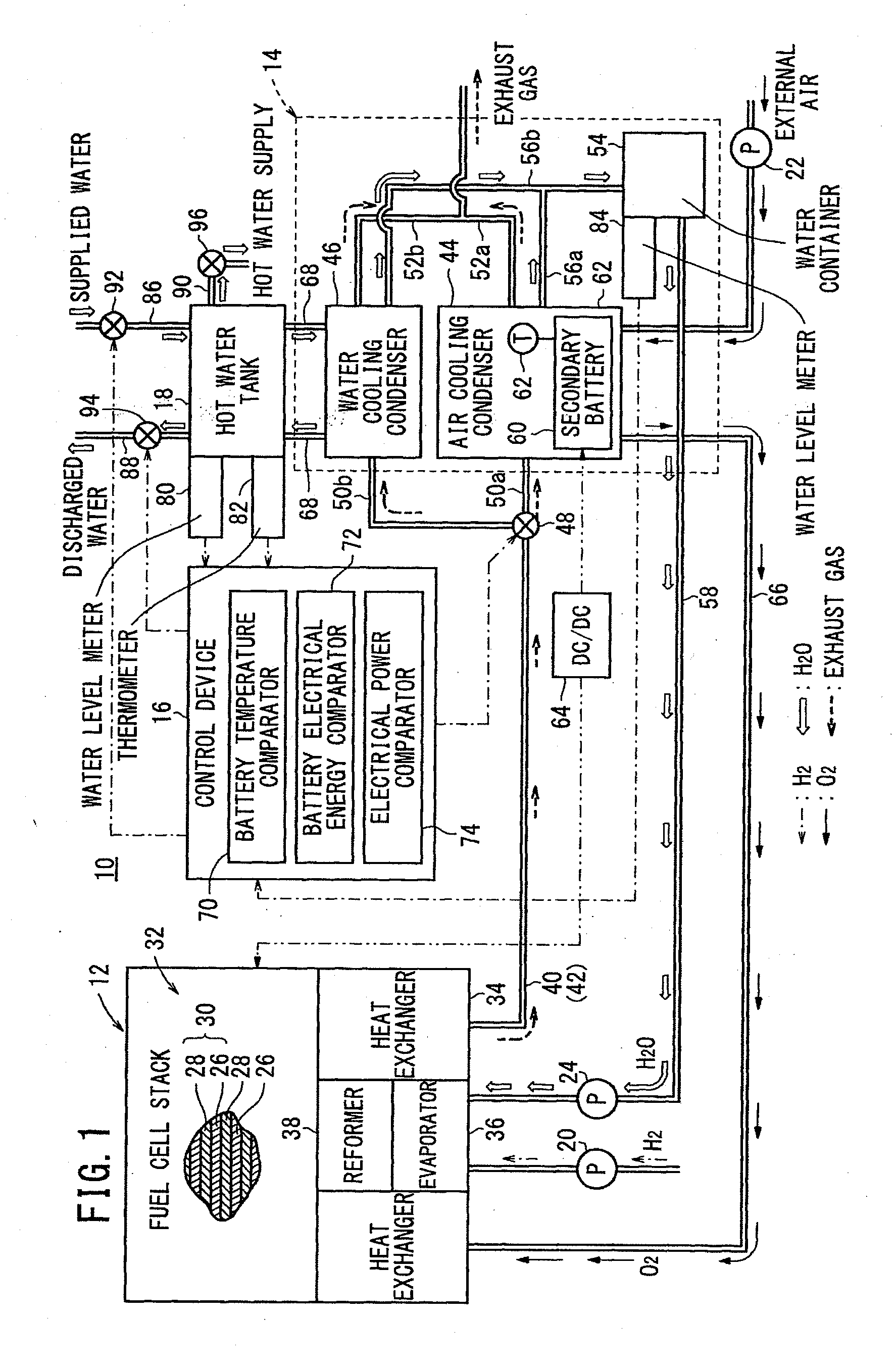
[0029]As schematically shown in FIG. 1, the fuel cell system 10 includes a fuel cell module 12 for generating electrical energy in power generation by electrochemical reactions of a fuel gas (hydrogen gas) and an oxygen-containing gas (air), a condenser 14 for condensing water vapor in an exhaust gas discharged from the fuel cell module 12 by heat exchange between the exhaust gas and a coolant to collect the condensed water and supplying the collected condensed water to the fuel cell module 12, a control device 16, and a hot water tank (storage unit) 18 for storing water as the coolant.

[0030]The fuel cell module 12 is connected to a fuel gas supply apparatus (including a fuel gas pump) 20 for supplying a raw fuel (e.g., city gas) to the fuel cell module 12, an oxygen-containing gas s...

second embodiment

[0096]FIG. 5 is a diagram schematically showing a fuel cell system 100 according to the present invention.

[0097]The constituent elements that are identical to those of the fuel cell system according to the first embodiment are labeled with the same reference numerals, and description thereof will be omitted.

[0098]In the fuel cell system 100, an air cooling fan 102 is attached to the air cooling condenser 44. Therefore, in the air cooling condenser 44, the external air (oxygen-containing gas) forcibly supplied from the air cooling fan 102 cools the exhaust gas discharged from the fuel cell stack 32, and the external air is used as a coolant during discharging of the secondary battery 60.

[0099]In this manner, in the second embodiment, the same advantages as in the case of the first embodiment are obtained. For example, water self-sustaining operation and thermally self-sustaining operation are facilitated, and overall efficiency and load following performance are improved advantageous...


PUM

PropertyMeasurementUnit
operating temperatureaaaaaaaaaa
electrical energyaaaaaaaaaa
temperatureaaaaaaaaaa

Abstract

A fuel cell system includes a fuel cell module for generating electrical energy by electrochemical reactions of a fuel gas and an oxygen-containing gas, a condenser for condensing water vapor in an exhaust gas discharged from the fuel cell module by heat exchange between the exhaust gas and a coolant to collect the condensed water and supplying the collected condensed water to the fuel cell module. The condenser includes an air cooling condensing mechanism using the oxygen-containing gas as the coolant. The air cooling condensing mechanism includes a secondary battery for inducing endothermic reaction during charging and inducing exothermic reaction during discharging.

Description

TECHNICAL FIELD[0001]The present invention relates to a fuel cell system including a fuel cell module for generating electrical energy by electrochemical reactions of a fuel gas and an oxygen-containing gas, and a condenser for condensing water vapor in an exhaust gas discharged from the fuel cell module by heat exchange between the exhaust gas and a coolant to collect the condensed water and supplying the collected condensed water to the fuel cell module.BACKGROUND ART[0002]Typically, a solid oxide fuel cell (SOFC) employs a solid electrolyte of ion-conductive oxide such as stabilized zirconia. The solid electrolyte is interposed between an anode and a cathode to form an electrolyte electrode assembly. The electrolyte electrode assembly is interposed between separators (bipolar plates). In use, normally, predetermined numbers of the electrolyte electrode assemblies and the separators are stacked together to form a fuel cell stack.[0003]As the fuel gas supplied to the fuel cell, nor...

Claims


Application Information

Patent Timeline
Patent Type & Authority Applications(United States)
IPC IPC(8): H01M16/00H01M10/39H01M8/06H01M8/04H01M8/00
CPCH01M16/006H01M8/04164H01M2250/402H01M8/0618H01M8/04007H01M10/3909H01M8/04014H01M10/399H01M10/613H01M10/615H01M10/63H01M10/66H01M2008/1293H01M2250/405Y02B90/10Y02E60/10Y02E60/50
Inventor OGAWA, TETSUYA
Owner HONDA MOTOR CO LTD
Why Eureka
Try Eureka