

Machine controller
a technology of machine controller and controller body, which is applied in the direction of electric controller, total factory control, programme control, etc., can solve the problems of overloading of power supply equipment in the facility, motors consume large amounts of power, and the maximum power consumption in the entire facility may become larger, so as to reduce the maximum power consumption in the facility without lowering productivity
- Summary
- Abstract
- Description
- Claims
- Application Information
AI Technical Summary
Benefits of technology
Problems solved by technology
Method used
Image

Examples
first embodiment
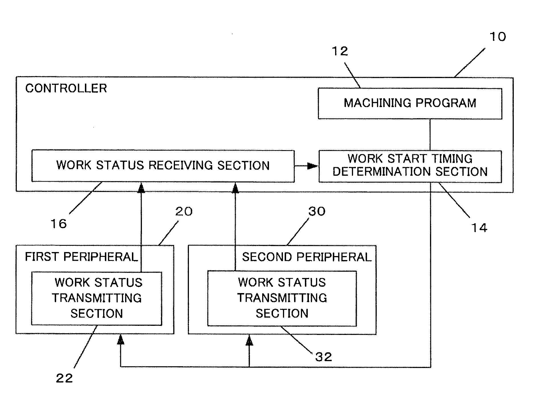
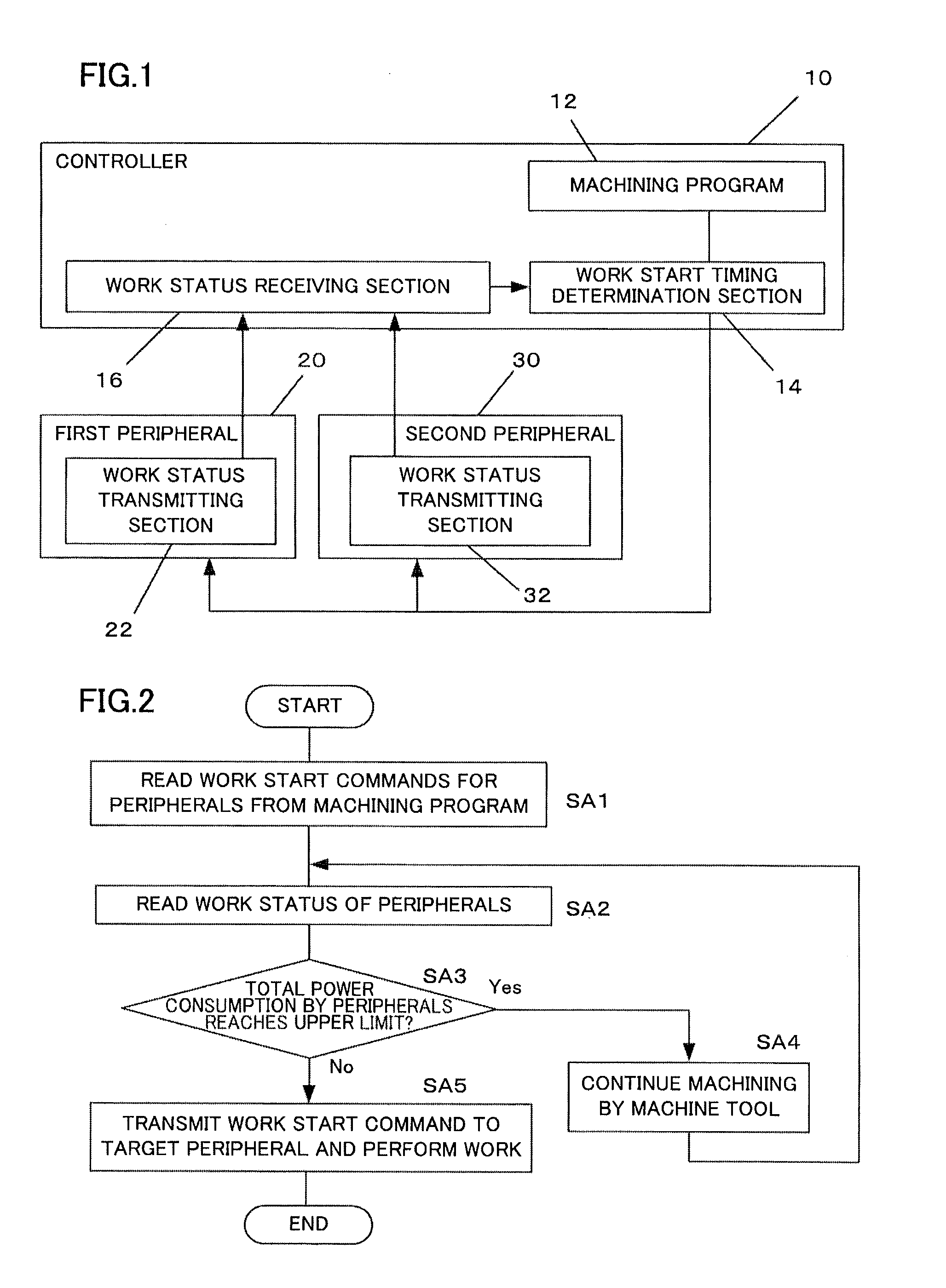
[0025]In this embodiment, each machine tool is connected to a network, and therefore the controller for each machine tool identifies the work status of peripherals and determines work start timing for these peripherals. Instead of machine tools, industrial machines such as injection molding machines, electric discharge machines, and pressing machines may be used. Each machine tool has a numerical controller provided with a network interface. Each peripheral has a controller provided with a network interface, such as a numerical controller or programmable logic controller (PLC). An intercommunication means is not limited to a network, and a means using input / output signals may be employed.
[0026]In addition to providing normal functions for controlling operations of the machine tools, the numerical controllers for the machine tools perform processing for receiving the peripheral work status and deciding the peripheral work start timing. In addition to providing normal functions for co...
second embodiment
[0052]In this embodiment, to monitor the maximum peripheral power, the maximum number of peripherals that operate simultaneously is preset based on, for example, the maximum power consumption in a facility and the number of installed peripherals and machine tools. Then, peripheral work start command timing is set such that the number of peripherals that operate simultaneously is smaller than or equal to the maximum number.
[0053]FIG. 6 is a flowchart illustrating a flow of processing performed by this embodiment for adjusting peripheral work start timing. Each step will be described below.[0054](Step SC1) The work start timing determination section 14 in the machine tool controller 10 reads work start commands for the peripherals 20, 30 from the machining program 12.[0055](Step SC2) The work status of the peripherals 20, 30 is read.[0056](Step SC3) A determination is made as to whether or not the number of currently working peripherals reaches the predetermined maximum number. If the...
third embodiment
[0060]In the above first and second embodiments, timing of peripheral work start is controlled by monitoring the maximum power consumption and the number of peripherals that operate simultaneously. If a work start command can be delayed without limitation, however, the following may occur: For example, if a peripheral is a robot that changes workpieces, the next machining command is issued before workpieces are changed, as a result, machining of a machined workpiece is erroneously started. For this reason, this embodiment imposes a limitation on peripheral work start timing to be delayed in a machining program.
[0061]FIG. 7 illustrates an example of a machining program in this embodiment. For example, when a robot that changes workpieces is used as a first peripheral, a work start command range starting point is set immediately after the workpiece change work in the previous machining and a work start command range ending point is set before the machining completion command in the cu...
PUM
 Abstract
Description
Claims
Application Information