

Sample fixing member for atomic force microscope
- Summary
- Abstract
- Description
- Claims
- Application Information
AI Technical Summary
Benefits of technology
Problems solved by technology
Method used
Image

Examples
first preferred embodiment
[0031]A preferred embodiment (hereinafter sometimes referred to as “first preferred embodiment”) of the carbon nanotube aggregate that may be included in the sample fixing member for an atomic force microscope of the present invention includes a plurality of carbon nanotubes, in which: the carbon nanotubes each have a plurality of walls; the distribution width of the wall number distribution of the carbon nanotubes is 10 walls or more; and the relative frequency of the mode of the wall number distribution is 25% or less.
[0032]The distribution width of the wall number distribution of the carbon nanotubes is 10 walls or more, preferably from 10 walls to 30 walls, more preferably from 10 walls to 25 walls, still more preferably from 10 walls to 20 walls.
[0033]The “distribution width” of the wall number distribution of the carbon nanotubes refers to a difference between the maximum wall number and minimum wall number in the wall numbers of the carbon nanotubes. When the distribution wid...
second preferred embodiment
[0044]Another preferred embodiment (hereinafter sometimes referred to as “second preferred embodiment”) of the carbon nanotube aggregate that may be included in the sample fixing member for an atomic force microscope of the present invention includes a plurality of carbon nanotubes, in which: the carbon nanotubes each have a plurality of walls; the mode of the wall number distribution of the carbon nanotubes is present at a wall number of 10 or less; and the relative frequency of the mode is 30% or more.
[0045]The distribution width of the wall number distribution of the carbon nanotubes is preferably 9 walls or less, more preferably from 1 walls to 9 walls, still more preferably from 2 walls to 8 walls, particularly preferably from 3 walls to 8 walls.
[0046]The “distribution width” of the wall number distribution of the carbon nanotubes refers to a difference between the maximum wall number and minimum wall number of the wall numbers of the carbon nanotubes. When the distribution wid...
example 1
[0075]An Al thin film (thickness: 10 nm) was formed on a silicon substrate (manufactured by KST, wafer with a thermal oxide film, thickness: 1,000 μm) with a vacuum deposition apparatus (JEE-4X Vacuum Evaporator manufactured by JEOL Ltd.). After that, the resultant was subjected to an oxidation treatment at 450° C. for 1 hour. Thus, an Al2O3 film was formed on the silicon substrate. An Fe thin film (thickness: 2 nm) was further deposited from the vapor onto the Al2O3 film with a sputtering apparatus (RFS-200 manufactured by ULVAC, Inc.) to form a catalyst layer.
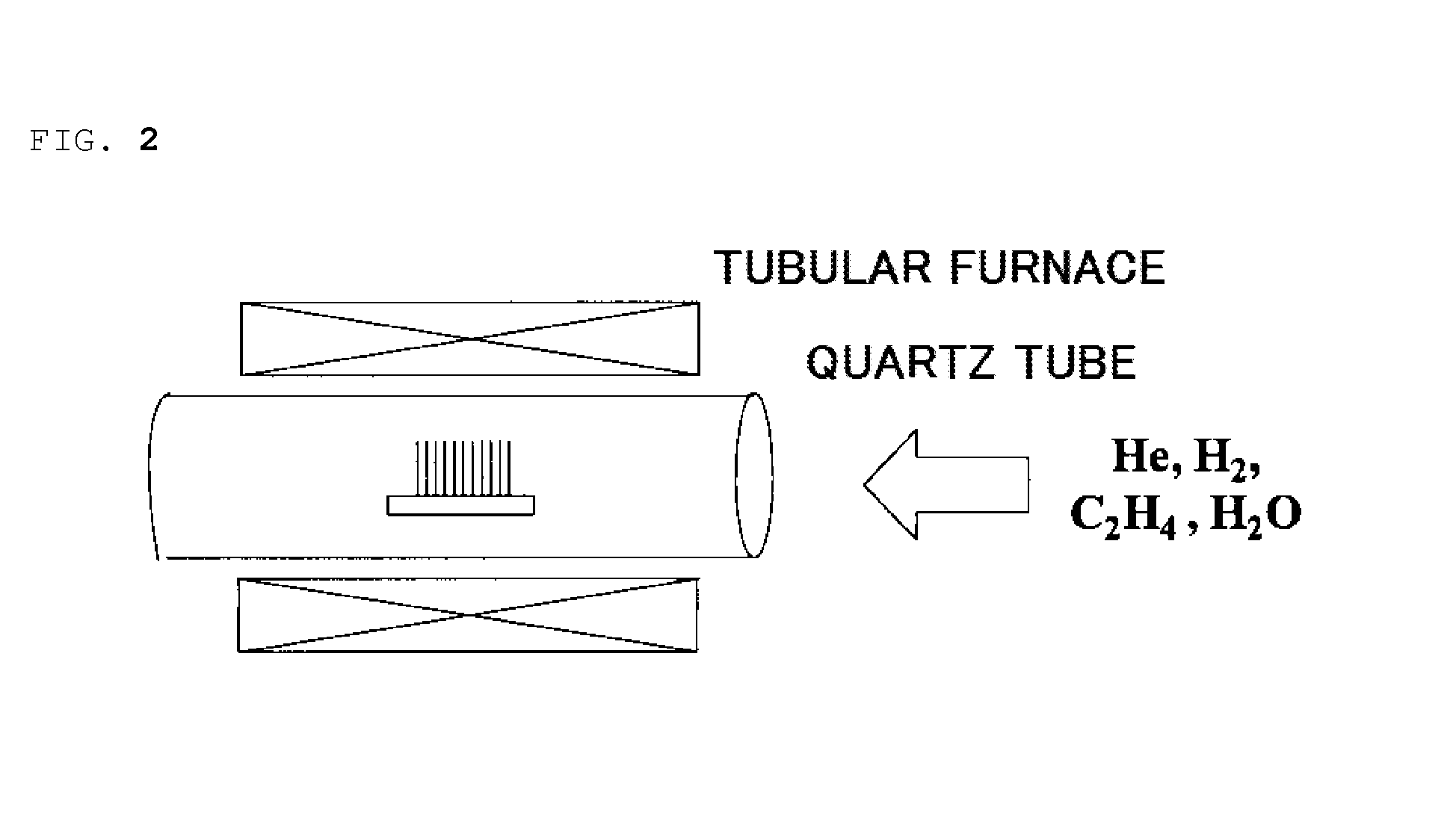
[0076]Next, the resultant silicon substrate with the catalyst layer was cut and mounted in a quartz tube having a diameter of 30 mm, and a helium / hydrogen (120 / 80 sccm) mixed gas whose moisture content had been held at 350 ppm was flowed into the quartz tube for 30 minutes to replace the inside of the tube. After that, a temperature in the tube was increased with an electric tubular furnace to 765° C. in 35 minutes in a stepw...
PUM
 Abstract
Description
Claims
Application Information