Energy plant and parts of an energy plant

a technology of energy plants and parts, applied in water-power plants, machines/engines, electric generator control, etc., can solve the problems of reducing the efficiency of the leading edge, and not developing effective suction on the opposite sid

Inactive Publication Date: 2015-01-15
SUS ENERGY
View PDF18 Cites 3 Cited by
  • Summary
  • Abstract
  • Description
  • Claims
  • Application Information

AI Technical Summary

Benefits of technology

[0012]The object of the invention is to provide new solutions for providing an energy plant and parts of an energy plant for utilizing water movement, with which the problems of the prior art energy plants can be avoided or reduced.
[0015]a mechanical or hydraulic transmission for increasing the relative speed of rotation; and

Problems solved by technology

Certain problems are related to the prior art wave energy plants.
It develops overpressure to the front / flow side of the plate but the more important suction on the opposite side does not develop effectively because there is no increased flow velocity along the opposite surface.
In addition, the flow around the side edges (see 4 of the enclosed FIG. 2) causes turbulence and reduces the small back side suction even further.
Also in case of angle of attack of flow not being straight against the axis line of plate, flow around the leading edge reduces the efficiency even further.
When energy of water movement is captured to moving surfaces like planes or wings, or floating volumes like buoys, there is a problem of very slow speed with high forces.
Therefore straight drive generators would be extremely large machinery due to magnetic saturation and increase of speed is needed.
Increased flow resistance cuts the system's ability to react to and capture transient energy peaks.
Long lines make efficient use of hydraulic accumulators difficult.
All components and lines also add space requirements and size, thus increasing costs.
Generator systems regularly stopping and restarting with waves cause harmful peaks to mains network lowering the usability of entire plants.
The underwater electric connections are done with technology known from dry environment and they are therefore impractical in underwater environment.
They are also impossible to connect / disconnect while generators are running.
Making high power connections in wet environment by divers, remotely operated underwater vehicles or other remote equipment is also too risky because of possible electric leaks and shortages.
Therefore replacing non-functional units is very costly and requires shutdown of entire plant.
As a consequence, the systems are very difficult to maintain on site as would be preferred.

Method used


Image

  • Energy plant and parts of an energy plant
  • Energy plant and parts of an energy plant
  • Energy plant and parts of an energy plant

Examples


Embodiment Construction

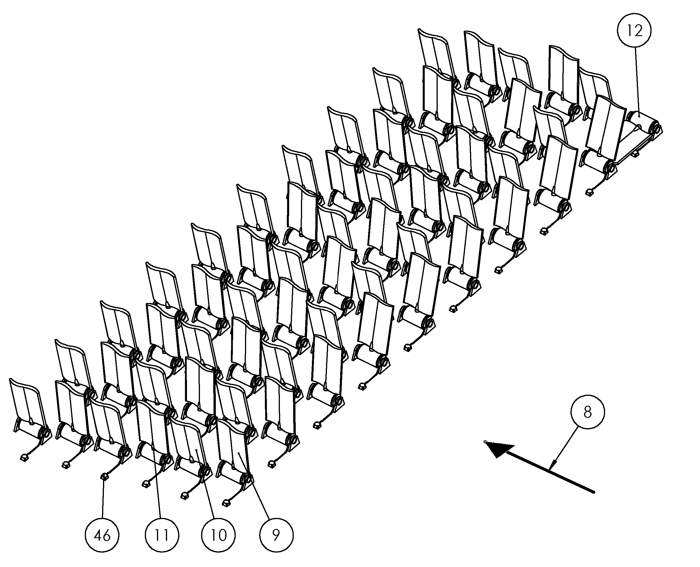
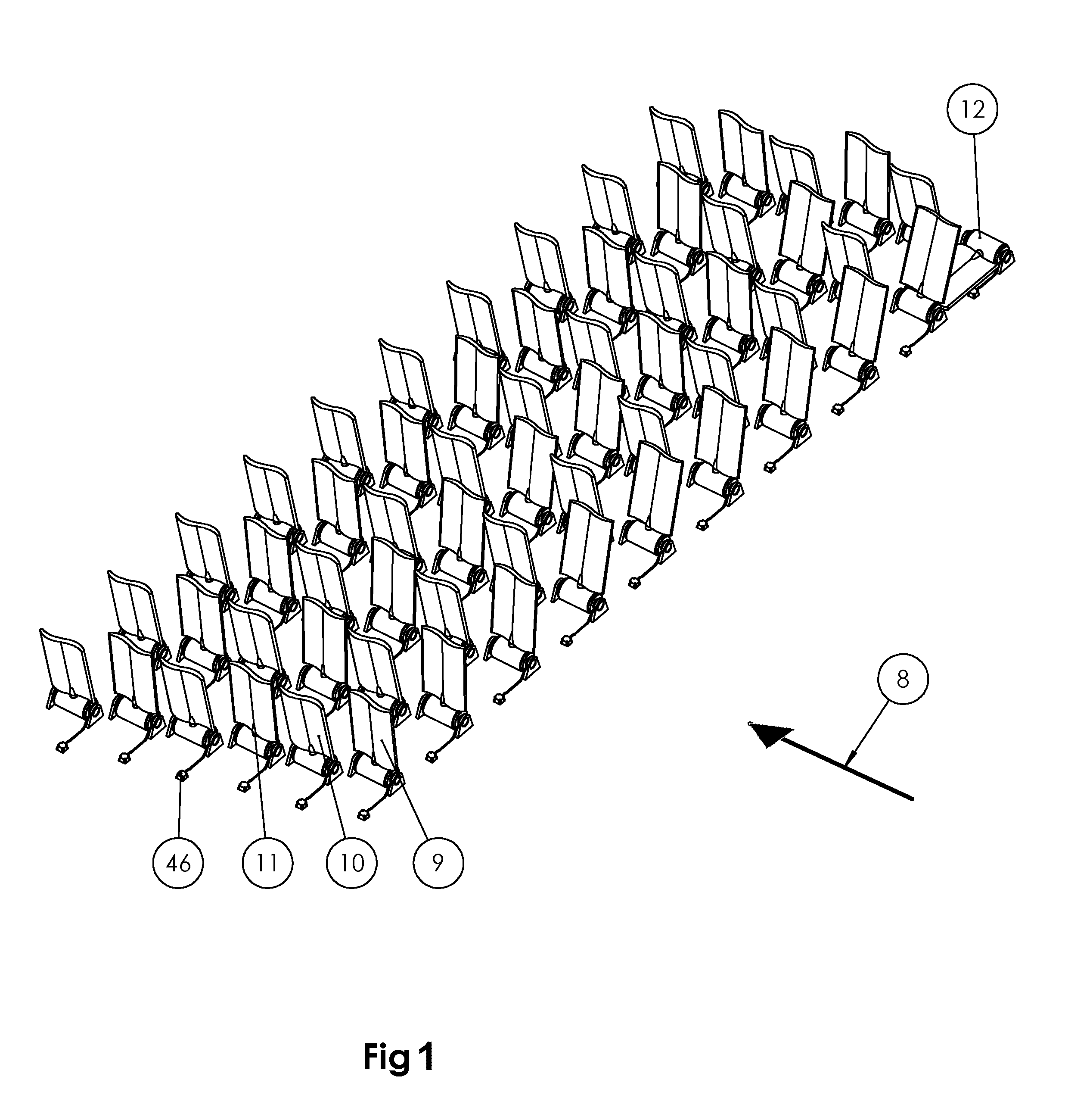
[0043]FIG. 1 illustrates an exemplary embodiment of an energy plant according to the invention. The energy plant has a matrix of energy production units, each comprising an underwater wing 9, 10, 11, a hinge-type energy converter 12 and an inductive connector 46 which connected to the generator of the converter with a cable. With remote control, an underwater wing or plate can be turned to preferred position. The direction of the water flow is marked with arrow 8. The wings preferably move so that their position alternates between both sides of the vertical position. The efficiency is highest at the vertical position of the wing, and getting lower when the wing gets more apart from the vertical position. This is e.g. because the water flow is smaller at the vicinity of the bottom.

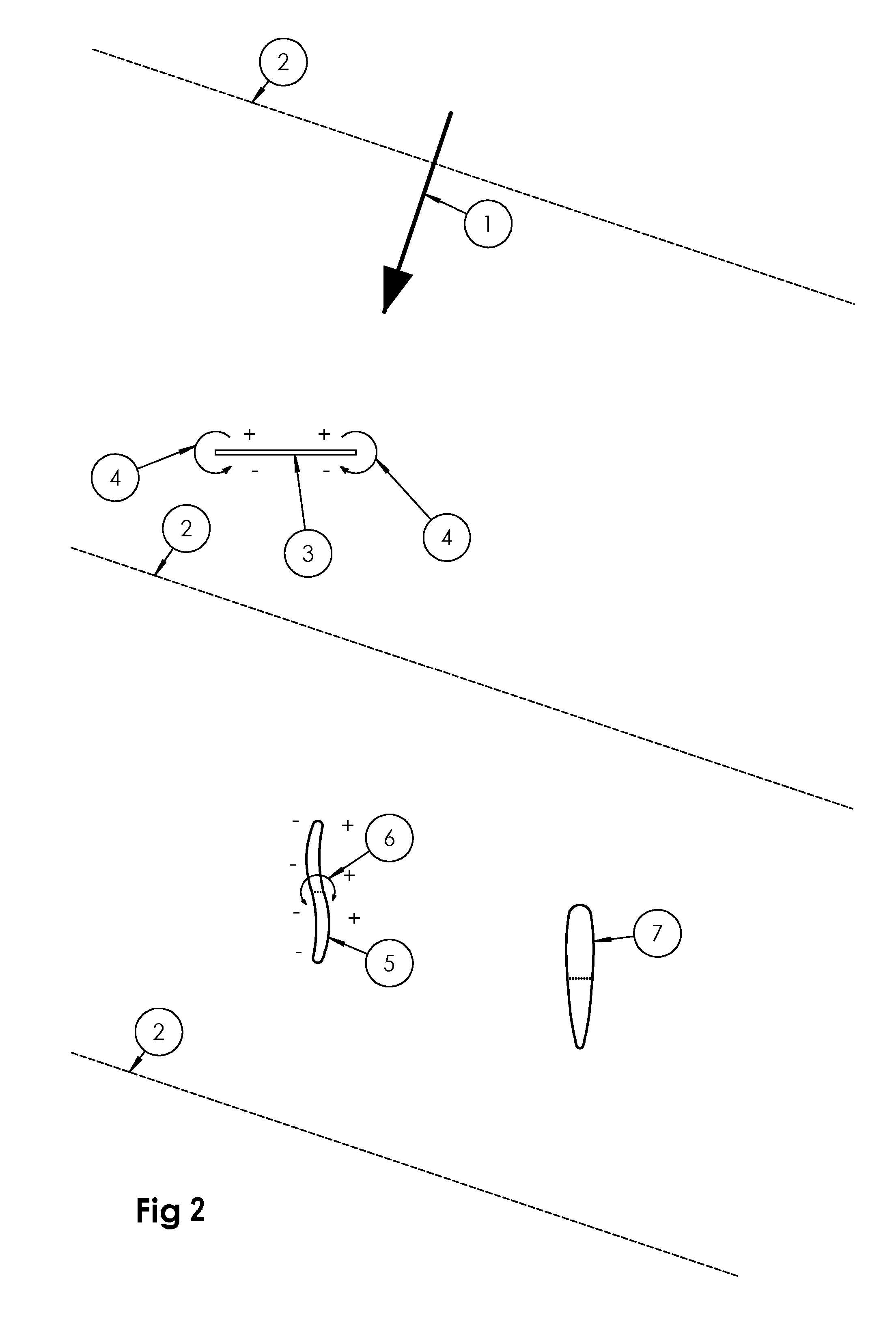
[0044]FIG. 2 illustrates a prior art underwater plate 3, and two exemplary embodiments of an underwater wing 5, 7 according to the invention. The prior art plate has a surface with a planar shape, whereby t...


PUM


Abstract

The invention pertains to underwater energy plants utilizing water movement due to e.g. waves, tide or stream. The invention also relates to parts of such a plant, namely an underwater wing for capturing wave energy, apparatus to convert the mechanical energy to electrical energy, and a connector for transferring the electrical energy. In certain embodiments of the invention, a wing causes a moment around hinging axis due to water flow with autonomous or tethered in-hinge electric generator and underwater attachable high power electric connector based on inductive transfer of energy.

Description

FIELD OF INVENTION[0001]The invention pertains to underwater energy plants utilizing water movement due to e.g. waves, tide or stream. The invention also relates parts of such a plant, namely an underwater wing for capturing energy of water movement, apparatus to convert the mechanical energy to electrical energy, and a connector for transfer-ring the electrical energy.BACKGROUND TECHNOLOGY[0002]A prior art solution for providing a wave energy plant is disclosed in document WO2004 / 097212. The wave energy plant has two or more production units and the water mass of the water basin is adapted to actuate production units or their parts submersed at the bottom of the water basin. The production units are used for transforming the kinetic energy of the water mass into other form of energy like electric energy, mechanical energy or pressure of an intermediate agent.[0003]Certain problems are related to the prior art wave energy plants. Any profile in flow causes forces due to increased pr...

Claims


Application Information

Patent Timeline
Patent Type & Authority Applications(United States)
IPC IPC(8): F03B13/18H02J5/00F03B13/10
CPCF03B13/182H02J5/005F03B13/10E02B9/08H01F38/14F03B13/264F03B17/061F05B2240/30F05B2240/40F05B2260/74F03B17/06Y02E10/30Y02E10/20
Inventor SILTALA, TIMO
Owner SUS ENERGY
Why Eureka
Try Eureka