Amoled driving circuit and driving method thereof, and display device

a technology of amoled driving circuit and display device, which is applied in the field of display technology, can solve the problems of low charging speed, small isub>data/sub>, and different driving currents, and achieve the effect of increasing the current for charging the charging uni

Active Publication Date: 2015-01-15
CHENGDU BOE OPTOELECTRONICS TECH CO LTD +1
View PDF7 Cites 5 Cited by
  • Summary
  • Abstract
  • Description
  • Claims
  • Application Information

AI Technical Summary

Benefits of technology

[0034]With configuration of the above circuit structure according to the present invention, a ratio between the data current of the data line and the driving current of the light emitting device is adjustable, and thus the ratio between the two currents may be increased, that is, the ratio between the data current of the data line and the driving current of the light emitting device may be increased by adjusting the current coefficients of the driving transistors in the driving unit, thus the current for charging the charging unit may be increased, and the problem of low charging speed and long charging time of the AMOLED driving circuit to the capacitor may be effectively solved, so that the AMOLED driving circuit is suitable for AMOLED display in high resolution and high refresh frequency.

Problems solved by technology

If the threshold voltage VTH of the driving transistor of the pixel drifts over time, the driving current IOLED that drives the OLED to emit light may change, resulting in afterimage.
The driving current IOLED may also be different due to difference in operating voltage between OLEDs caused by non-uniformity of the OLED devices.
Accordingly, IDATA is also small, charging speed is low due to large capacitance of the storage capacitor, and charging time is especially very long in the condition of low gray level, resulting in not suitable for AMOLED display in high resolution and high refresh frequency.

Method used


Image

  • Amoled driving circuit and driving method thereof, and display device
  • Amoled driving circuit and driving method thereof, and display device
  • Amoled driving circuit and driving method thereof, and display device

Examples


first embodiment

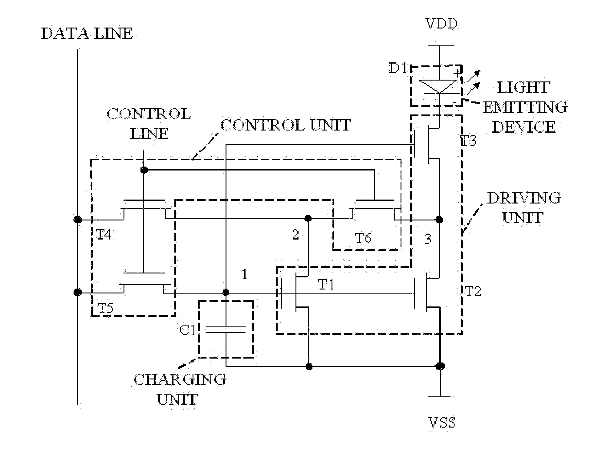
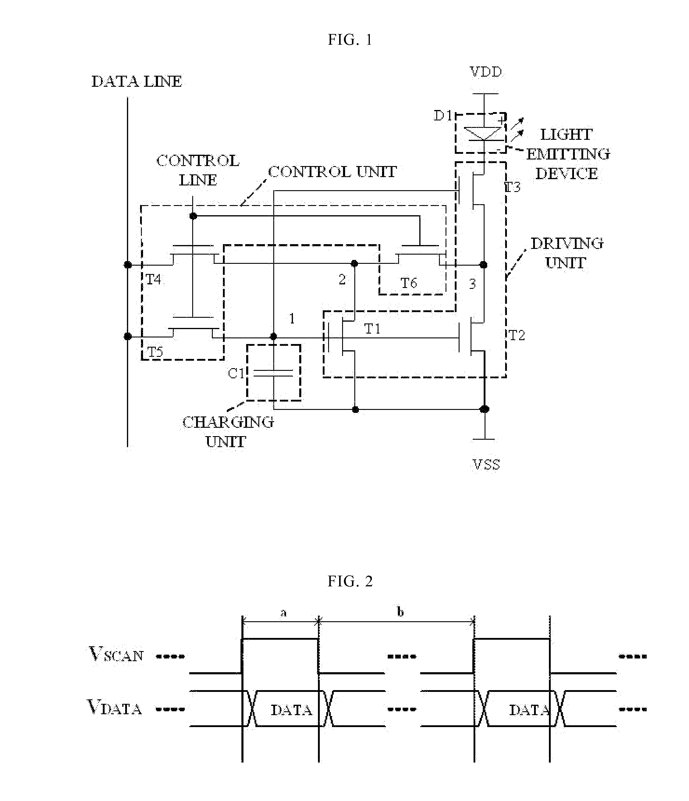
[0041]FIG. 1 is a diagram illustrating a circuit structure of an AMOLED driving circuit according to the present invention. As shown in FIG. 1, the AMOLED driving circuit includes a control unit, a charging unit, a driving unit and a light emitting device D1. The control unit is connected to a data line and a control line, and the control unit is connected to the driving unit via a first node 1, a second node 2 and a third node 3. The charging unit is connected to the driving unit via the first node 1, and the charging unit is connected to a first power source VSS. The driving unit is connected to the first power source VSS, and the driving unit is connected to one end of the light emitting device D1. The other end of the light emitting device D1 is connected to a second power source VDD. When a first control signal flows in the control line, in response to the first control signal, the control unit controls a current from the data line so as to charge the charging unit through the ...

second embodiment

[0057]FIG. 5 is an AMOLED driving circuit according to the present invention. As shown in FIG. 5, the AMOLED driving circuit includes a control unit, a charging unit, a driving unit and a light emitting device D1. More specifically, the control unit includes a first switching transistor T4, a second switching transistor T5 and a third switching transistor T6. The charging unit includes a storage capacitor C1. The driving unit includes a first driving transistor T1, a second driving transistor T2 and a third driving transistor T3. The control unit is connected to a data line and a control line, and the control unit is connected to the driving unit via a first node 1, a second node 2 and a third node 3. The charging unit is connected to the driving unit via the first node 1, and the charging unit is connected to a first power source VDD. The driving unit is connected to one end of the light emitting device D1, and the driving unit is connected to the first power source VDD. The other ...

third embodiment

[0068]In the present invention, there is provided a driving method, the driving method may be based on an AMOLED driving circuit including a control unit, a charging unit, a driving unit and a light emitting device, the driving method includes:

[0069]Step 101, when a first control signal flows in a control line, in response to the first control signal, the control unit controls a current from a data line so as to charge the charging unit through the driving unit.

[0070]More specifically, the control unit includes a first switching transistor, a second switching transistor and a third switching transistor. The driving unit includes a first driving transistor, a second driving transistor and a third driving transistor. The charging unit includes a storage capacitor. The step of the control unit controlling a current from a data line so as to charge the charging unit through the driving unit includes: the first switching transistor, the second switching transistor and the third switching...


PUM


Abstract

An AMOLED driving circuit, a driving method and a display device, wherein a control unit is connected to a data line and a control line, and is connected to a driving unit via first, second and third nodes; a charging unit is connected to the driving unit via the first node, and is connected to a first power source; the driving unit is connected to one end of a light emitting device, and is connected to the first power source; the other end of the light emitting device is connected to a second power source. The control unit controls a current so as to charge the charging unit through the driving unit, and controls the charging unit so as to supply a voltage to the driving unit through the first node, so that the driving unit is driven by the voltage and drives the light emitting device to emit light.

Description

FIELD OF THE INVENTION[0001]The present invention relates to the field of display technology, and more particularly, to an AMOLED driving circuit, a driving method of the AMOLED driving circuit and a display device.BACKGROUND OF THE INVENTION[0002]With development of display technology, application of active matrix organic light emitting diode (AMOLED) panel becomes more and more important. A light emitting device of AMOLED is an organic light emitting diode (OLED).[0003]Driving schemes of the OLED pixel circuit may be classified into a voltage driving scheme (voltage type) and a current driving scheme (current type). For the voltage type AMOLED, if threshold voltages VTH of driving transistors between different pixel units are different, there is difference between driving currents IOLED driving the OLED to emit light between different pixel units. If the threshold voltage VTH of the driving transistor of the pixel drifts over time, the driving current IOLED that drives the OLED to...

Claims


Application Information

Patent Timeline
Patent Type & Authority Applications(United States)
IPC IPC(8): G09G3/32
CPCG09G3/3233G09G2320/0257G09G2320/045G09G3/3241G09G2300/0842G09G2300/0861G09G2320/0252
Inventor TANQI, XIAOJING
Owner CHENGDU BOE OPTOELECTRONICS TECH CO LTD
Why Eureka
Try Eureka