Method to control temperature of engine of generator system

a technology of engine and generator, applied in the direction of electric generator control, electric control, instruments, etc., can solve the problems of generator system not starting or performing as desired, generator system may require frequent maintenance, and engine may not reach the optimum operating temperatur

Inactive Publication Date: 2015-01-22
CATERPILLAR INC
View PDF4 Cites 5 Cited by
  • Summary
  • Abstract
  • Description
  • Claims
  • Application Information

AI Technical Summary

Problems solved by technology

The standby generator system may produce power over a power bus when there is an electrical failure.
However, at times, the generator systems may fail to start or perform as desired in the time of need.
Hence, the generator system may require frequent maintenance.
However, at times, the generator system may operate in under-load conditions.
During such conditions, the engine may not attain the optimum operating temperature.
Hence, over time, “slobbering” of the generator systems may be a problem encountered, when the generator system is lightly loaded.
Another problem encountered in the generator systems may be condensation resulting from humidity, unless the generator systems are fully enclosed.
The above-mentioned problems are not conducive to long life and good performance of the generator systems.
However, there is no solution disclosed to avoid wet-stacking or engine slobber, while the generator system is under load bank testing.

Method used


Image

  • Method to control temperature of engine of generator system
  • Method to control temperature of engine of generator system
  • Method to control temperature of engine of generator system

Examples


Embodiment Construction

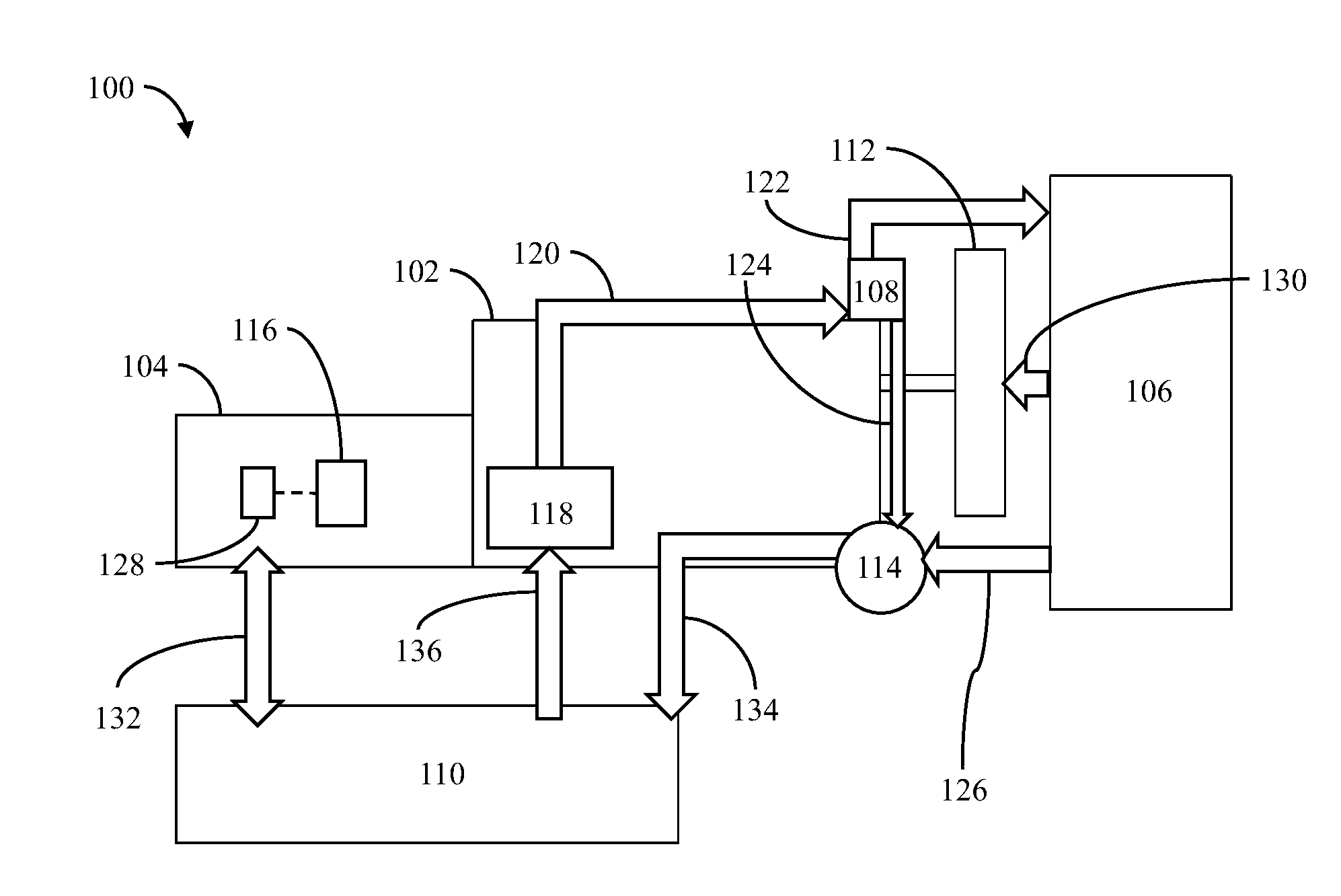
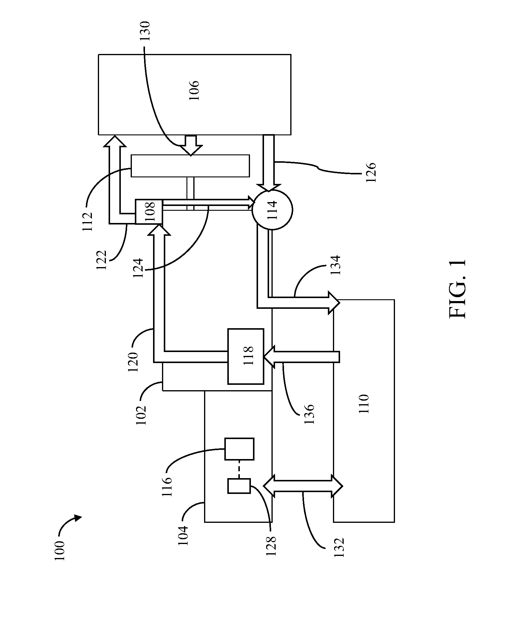
[0012]Referring to FIG. 1, there is shown a first generator system 100. The first generator system 100 includes an engine 102, a generator 104, a heat exchanger 106, a thermostat 108, a liquid load bank 110, a reversible fan 112, a pump 114, and a controller 116. Further, the engine 102 may be any type of combustion engine, such as a diesel engine, a gasoline engine, or a gaseous fuel-powered engine. The engine 102 includes an engine jacket 118. The engine jacket 118 is a water-cooled jacket, which is defined as the coolant flow path within the engine 102 passing through components such as, an engine block, a cylinder head, an oil cooler (engine / transmission), an exhaust gas recirculation system, and the like, to allow cooling of the engine components. The engine 102 is adapted to combust a mixture of fuel and air to produce mechanical power. The engine 102 is operatively coupled to the generator 104. Examples of the generator 104 may be an alternating current (AC) induction generat...


PUM


Abstract

A method to control temperature of an engine of a generator system during a load test is provided. The generator system includes a generator, one of a liquid load bank and an air resistive load bank, a reversible fan, and a heat exchanger. The method includes heating of the engine to a pre-determined temperature with heat supplied by the liquid load bank and the reversible fan or by the air resistive load bank via the reversible fan.

Description

TECHNICAL FIELD[0001]The present disclosure relates generally to generator systems. More specifically, the present disclosure relates to a method to control temperature of engine of the generator system.BACKGROUND[0002]A standby generator system provides backup power in the event that the main power service for a facility fails. The standby generator system may produce power over a power bus when there is an electrical failure. The facility will continue to have power despite the electrical failure when the backup power is provided over the power bus. The standby generator system may further be used to supplement the power on the power bus during periods of peak demand in applications such as a manufacturing plant.[0003]Typically, a generator system includes a combination of a generator and a prime mover (such as an engine). A mixture of fuel and air may be combusted within the engine to create a mechanical rotation of engine crankshaft, which drives the generator to produce electri...

Claims


Application Information

Patent Timeline
Patent Type & Authority Applications(United States)
IPC IPC(8): F02D35/02F02B63/04G01M15/05
CPCF02B63/04G01M15/05F02D35/02F02D41/021F02D2200/021G01M15/02
Inventor STENGL, ROBERT M.AHMED, ANIS
Owner CATERPILLAR INC
Why Eureka
Try Eureka