Regulated three-engined power plant for a rotary wing aircraft

a technology of rotary wing aircraft and power plant, which is applied in the direction of turbine/propulsion fuel control, air transportation, analog and hybrid computing, etc., can solve the problems of complex connections, system instability, and never reaching the setpoint value, and achieve the optimization of the power delivered by each engine. , the architecture between the computers of each of the engines can be simplified, and the effect of optimizing the power delivered

a technology of rotary wing aircraft and power plant, which is applied in the direction of turbine/propulsion fuel control, air transportation, analog and hybrid computing, etc., can solve the problems of complex connections, system instability, and never reaching the setpoint value, and achieve the optimization of the power delivered by each engine. , the architecture between the computers of each of the engines can be simplified, and the effect of optimizing the power delivered

US20150028153A1Active Publication Date: 2015-01-29EUROCOPTER

Image

  • Regulated three-engined power plant for a rotary wing aircraft
  • Regulated three-engined power plant for a rotary wing aircraft
  • Regulated three-engined power plant for a rotary wing aircraft

Examples


Embodiment Construction

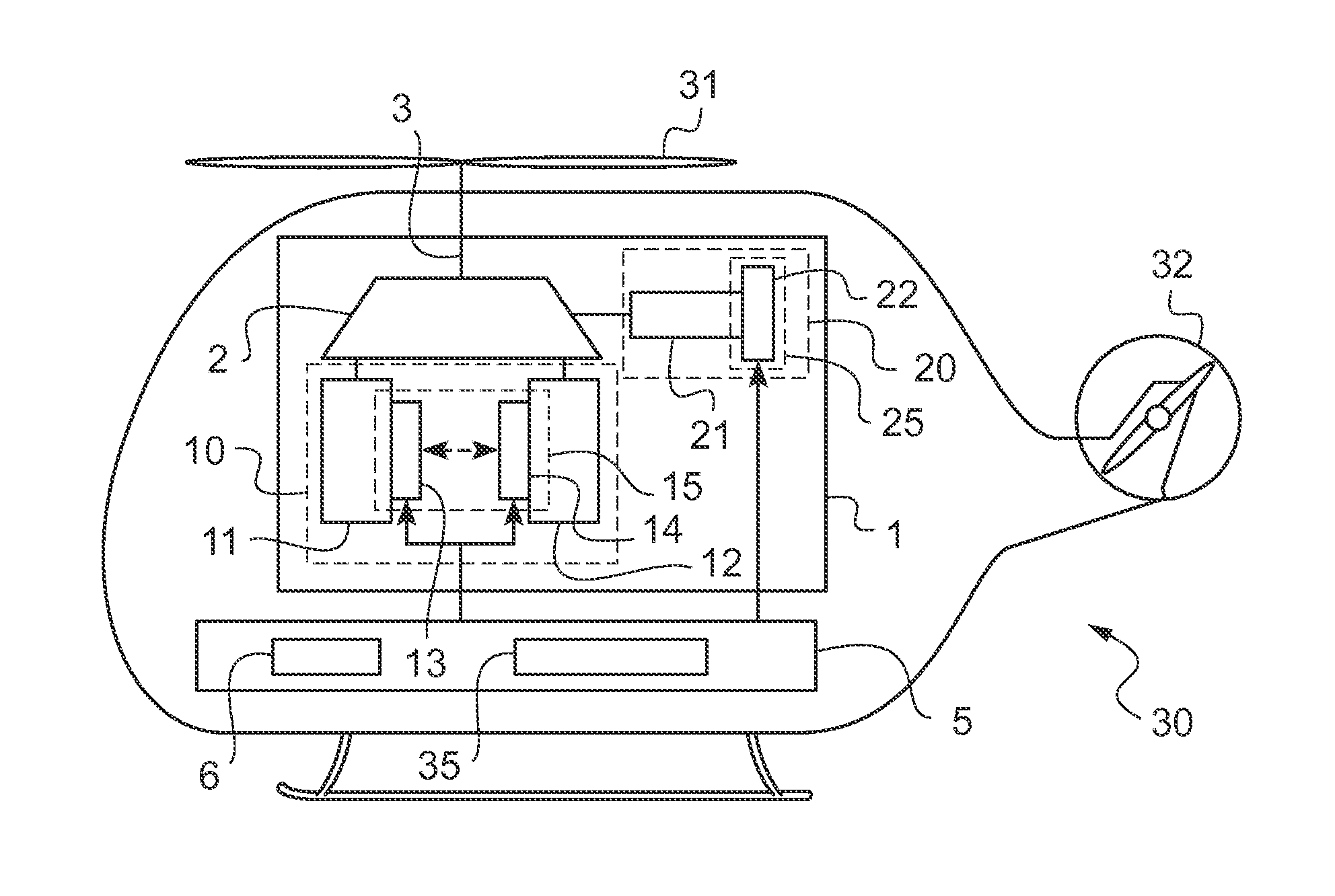
[0093]FIG. 1 shows a rotary wing aircraft 30 having a main rotor 31, a tail rotor 32, a power plant 1, and an avionics installation 5. The power plant 1 has a first engine group 10, a second engine group 20, and a main gearbox (MGB) 2. The two engine groups 10, 20 drive the MGB 2 mechanically in order to rotate a main outlet shaft 3 of the MGB 2. The main outlet shaft 3 is constrained to rotate with the main rotor 31 in order to provide the aircraft 30 with lift and possibly also propulsion.

[0094]The tail rotor 32 is also driven in rotation by the MGB 2 via a secondary outlet shaft from the MGB 2.

[0095]The first engine group 10 comprises two identical main engines 11 and 12 and a first regulator device 15. The first regulator device 15 comprises two main computers 13 and 14, each main computer 13, 14 being connected to a respective one of the main engines 11, 12, and the main computers 13, 14 are also connected to each other.

[0096]The second engine group 20 has a secondary engine 21...


PUM


Abstract

A power plant (1) having two engine groups (10, 20) and a main gearbox (MGB) (2), and a rotary wing aircraft (30) having such a power plant (1). Each engine group (10, 20) drives said MGB (2) mechanically to rotate a main outlet shaft (3) and, consequently, a main rotor (31) of said aircraft (30) at a frequency of rotation NR. A first engine group (10) has two main engines (11, 12) and is by a first setpoint NR* for said frequency of rotation NR, while a second engine group (20) has one secondary engine (21) and is regulated by a second setpoint W1* for power from said second engine group (20). The first engine group (10) is also regulated by a third setpoint W2f* for anticipating power such that said first engine group (10) and said second engine group (20) deliver the power needed at said main rotor (31).

Description

CROSS REFERENCE TO RELATED APPLICATION[0001]This application claims priority to French patent application No. FR 13 01749 filed on Jul. 23, 2013, the disclosure of which is incorporated in its entirety by reference herein.BACKGROUND OF THE INVENTION[0002](1) Field of the Invention[0003]The present invention lies in the field of powering rotary wing aircraft having a plurality of engines, and it lies more particularly in the field of regulating such a power plant.[0004]The present invention relates to a power plant for a rotary wing aircraft and to a rotary wing aircraft having such a power plant, and it also relates to a method of regulating such a power plant. The invention is particularly intended for regulating a power plant having three engines.[0005](2) Description of Related Art[0006]A power plant for a rotary wing aircraft generally has one or two engines and a main gearbox (MGB). Each engine drives the MGB mechanically in order to rotate at least one main outlet shaft of the...

Claims


Application Information

Patent Timeline
29 Jan 2015
Publication
US20150028153A1
IPC
B64D31/06; B64C27/00
CPC
B64C27/00; B64D31/06; B64C27/12; B64D35/08; F05D2270/05; F02C9/42; F05D2220/329; F05D2270/053
Inventors
ROSSOTTO, REGIS; BOIE, HANNO