Local Coil for a Coil System of a Magnetic Resonance Imaging System

local coil technology, applied in the field of local coil for a local coil system of a magnetic resonance imaging system, can solve the problems of not being able to not being able to solve the problem of complex or not being able to solve the problem at all, and avoid the cause of hot spots by restructuring the local coil, etc., to achieve excellent magnetic resonance compatibility, good heat dissipation, and good heat dissipation

Inactive Publication Date: 2015-01-29
SIEMENS AG
View PDF1 Cites 2 Cited by
  • Summary
  • Abstract
  • Description
  • Claims
  • Application Information

AI Technical Summary

Benefits of technology

[0019]The advantages achieved with the present embodiments are that, owing to the introduction of heat dissipation plates into the local coils of an MRI system, very good heat dissipation is achieved, and thus, the examination is more pleasant for the patient. Under specific examination circumstances, the use of close-contact local coils is thus

Problems solved by technology

Avoiding the cause of the hot spots by restructuring the local co

Method used


Image

  • Local Coil for a Coil System of a Magnetic Resonance Imaging System
  • Local Coil for a Coil System of a Magnetic Resonance Imaging System

Examples


Embodiment Construction

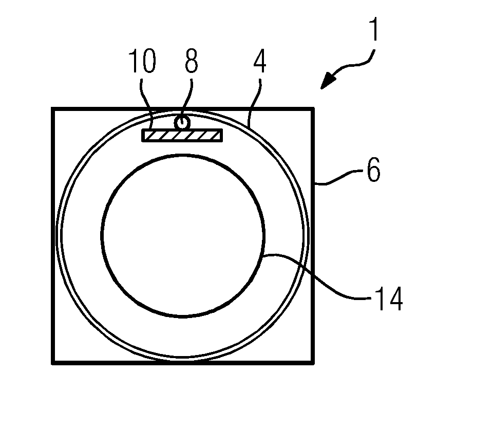
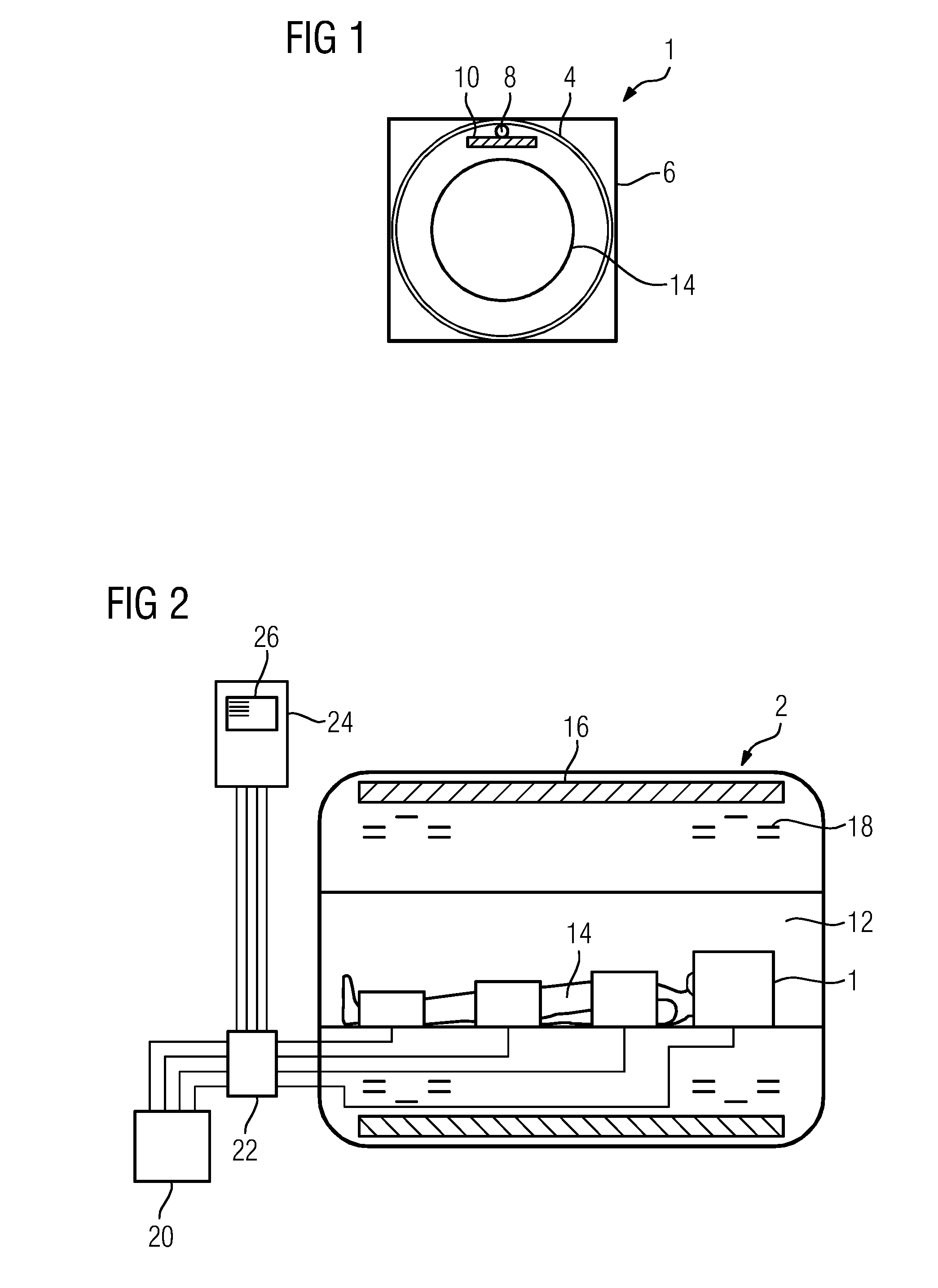
[0023]FIG. 1 illustrates a cross section through a local coil 1, as is used in a magnetic resonance imaging system 2. The magnetic resonance imaging system 2 will be explained in more detail in FIG. 2.

[0024]The local coil 1 has a coil 4 that is provided with connections (not illustrated in more detail) for supply with electrical signals. The coil 4 is arranged in a housing 6. During operation, the local coil 1 has a hot spot 8, at which a comparatively high heat develops. So as not to allow this heat to become unpleasant for a patient, a heat dissipation plate 10 is adhesively bonded into the housing 6 in a region of the hot spot 8. This may be done, for example, using adhesive strip or two-component adhesive.

[0025]The heat dissipation plate 10 is manufactured from aluminum nitride ceramic. The heat dissipation plate 10 thus has a specific heat conductivity of 180 W / mK and is electrically not conductive and not magnetic. The heat dissipation plate 10 has a surface area of more than ...


PUM


Abstract

A local coil for a coil system of a magnetic resonance imaging (MRI) system having a hot spot formed during operation of the magnetic resonance imaging system provides an MRI examination that is as pleasant as possible for a patient with a magnetic field strength that is as strong as possible. The local coil includes a heat dissipation plate arranged in a region of the hot spot.

Description

[0001]This application claims the benefit of DE 10 2013 214 330.3, filed on Jul. 23, 2013, which is hereby incorporated by reference in its entirety.BACKGROUND[0002]The present embodiments relate to a local coil for a coil system of a magnetic resonance imaging system having a hot spot forming during operation of the magnetic resonance imaging system.[0003]Magnetic resonance imaging (MRI) may be used to produce section images of the human or animal body that allow organs and many pathological organ changes to be assessed. MRI is based on very strong magnetic fields, produced in an MRI system, and alternating magnetic fields in the radio frequency range, with which specific atomic nuclei (e.g., hydrogen nuclei / protons) in the body are excited by resonance. As a result of this, an electrical signal is induced in a receiver circuit.[0004]MRI systems may have a transmitting unit that is provided for generating a substantially homogeneous radio-frequency field for exciting the nuclear sp...

Claims


Application Information

Patent Timeline
IPC IPC(8): G01R33/34
CPCG01R33/34092G01R33/3403A61B5/055G01R33/341
Inventor CANDIDUS, YVONNEJAHNS, KARSTENKESS, HELMUTKRAUS, WOLFGANGROTHARD, JORG
Owner SIEMENS AG
Why Eureka
Try Eureka