High frequency component and filter component

a high frequency component and filter technology, applied in the field of high frequency components, can solve the problems of difficult size reduction in the multilayer body and increase the size of the multilayer body, and achieve the effects of reducing resistance, increasing the effective cross-sectional area of the linear conductor, and reducing the loss of insertion of the high frequency componen

Active Publication Date: 2015-01-29
MURATA MFG CO LTD
View PDF8 Cites 6 Cited by
  • Summary
  • Abstract
  • Description
  • Claims
  • Application Information

AI Technical Summary

Benefits of technology

[0017]Of the plurality of linear conductors included in the transverse coil, two linear conductors including a same number of turns and being adjacent in the stacking direction may preferably be connected in parallel with each other through the interlayer connection conductors. Thus, the linear conductors included in the transverse coil can have a multilayer structure, the effective cross-sectional area of the linear conductors is increased, and the transverse coil has a reduced resistance. Accordingly, the LC resonant circuit has an increased Q value.
[0018]According to another preferred embodiment of the present invention, a filter component includes the above-described high frequency component and a filter circuit included in the high frequency component. The filter circuit may preferably include a plurality of LC resonant circuits each including the transverse coil. The transverse coils included in the LC resonant circuits may preferably be configured such that their winding axes are parallel or substantially parallel to each other and their coil openings overlap each other when viewed along the winding axes. Thus, because the multistage LC resonant circuits are electromagnetically coupled together through the transverse coils, the coupling between the LC resonant circuits (inter-resonator coupling) are adjustable by adjusting the shape of each of the transverse coils and the arrangement thereof. Accordingly, an attenuation pole and other elements in the filter characteristic of the filter component are effectively controlled.
[0019]The internal capacitor may preferably function as a capacitor for inter-resonator coupling between the plurality of LC resonant circuits. Thus, the wiring path connecting the multistage LC resonant circuits is shortened while the multistage LC resonant circuits are capacitive-coupled through the internal capacitors functioning as the capacitors for inter-resonator coupling. Accordingly, the insertion loss of the high frequency component is reduced, and a satisfactory filter characteristic is achieved.
[0020]The plurality of LC resonant circuits may preferably include an input-stage LC resonant circuit, an output-stage LC resonant circuit, and an intermediate-stage LC resonant circuit coupled between the input-stage LC resonant circuit and the output-stage LC resonant circuit. Each of the linear conductors included in the transverse coil included in the intermediate-stage LC resonant circuit may preferably have a width larger than that of each of the linear conductors included in each of the input-stage LC resonant circuit and the output-stage LC resonant circuit. With this configuration, the Q value of the intermediate-stage LC resonant circuit is improved, and the insertion loss of the high frequency component is significantly reduced.
[0021]In the high frequency component according to various preferred embodiments of the present invention, because the internal capacitor is arranged within the coil opening of the transverse coil when viewed along the winding axis of the transverse coil, the number of insulating layers required for the internal capacitor and the area thereof is reduced, and the size of the multilayer body is reduced. In addition, the connection wiring required to connect the transverse coil and the internal capacitor is shortened, and the conductive patterns of the transverse coil and the planar conductors of the internal capacitor are perpendicular or substantially perpendicular to each other. Accordingly, satisfactory high frequency characteristics is easily achieved.

Problems solved by technology

However, the increase in the size of the opening of the coil or in the number of turns of the coil may lead to an increased size of the multilayer body.
However, even with the use of the transverse coil or longitudinal coil as an inductor included in an LC circuit, size reduction in the multilayer body may be difficult, depending on the configuration of a capacitor included in the LC circuit.

Method used


Image

  • High frequency component and filter component
  • High frequency component and filter component
  • High frequency component and filter component

Examples


Embodiment Construction

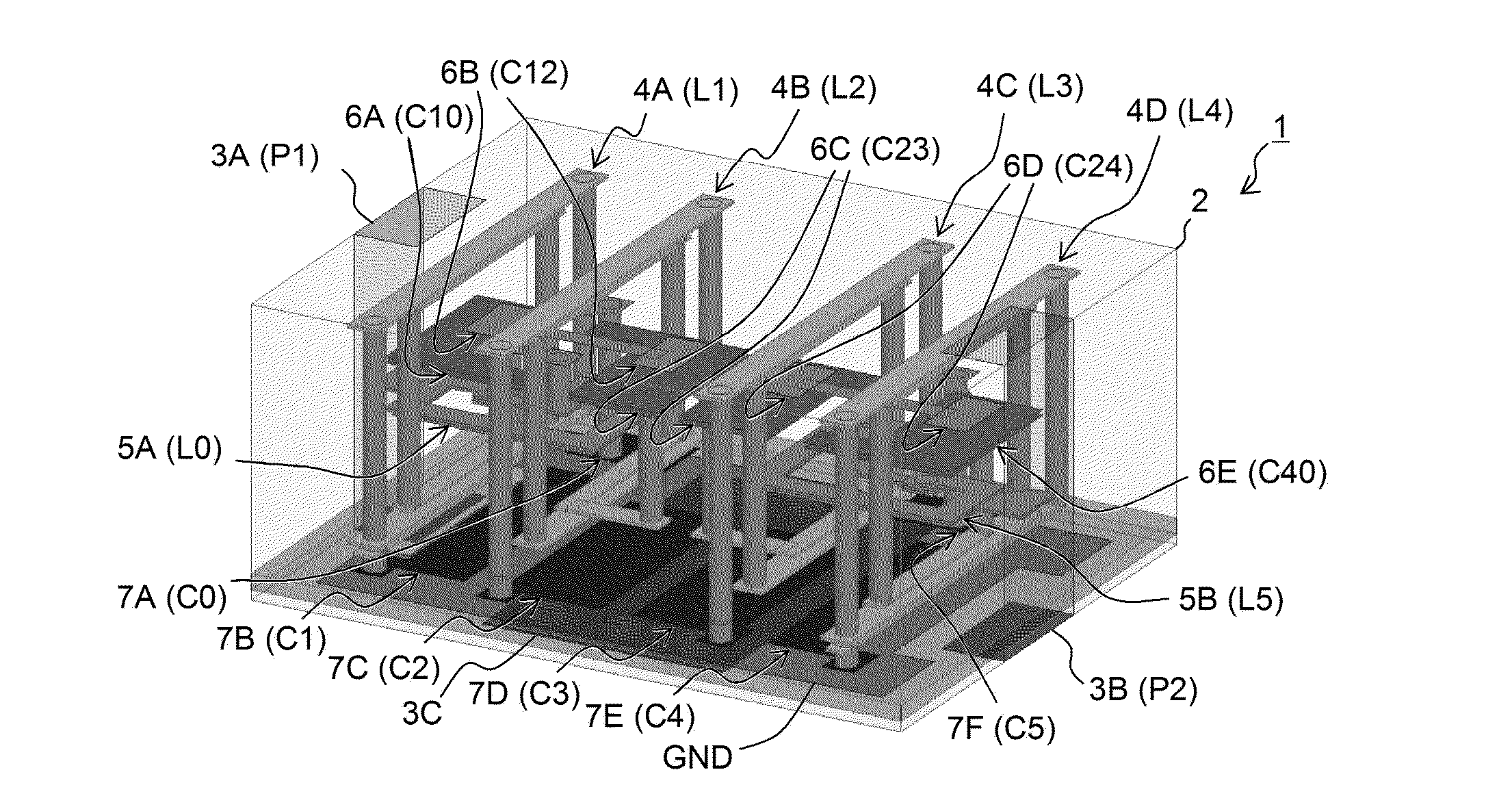
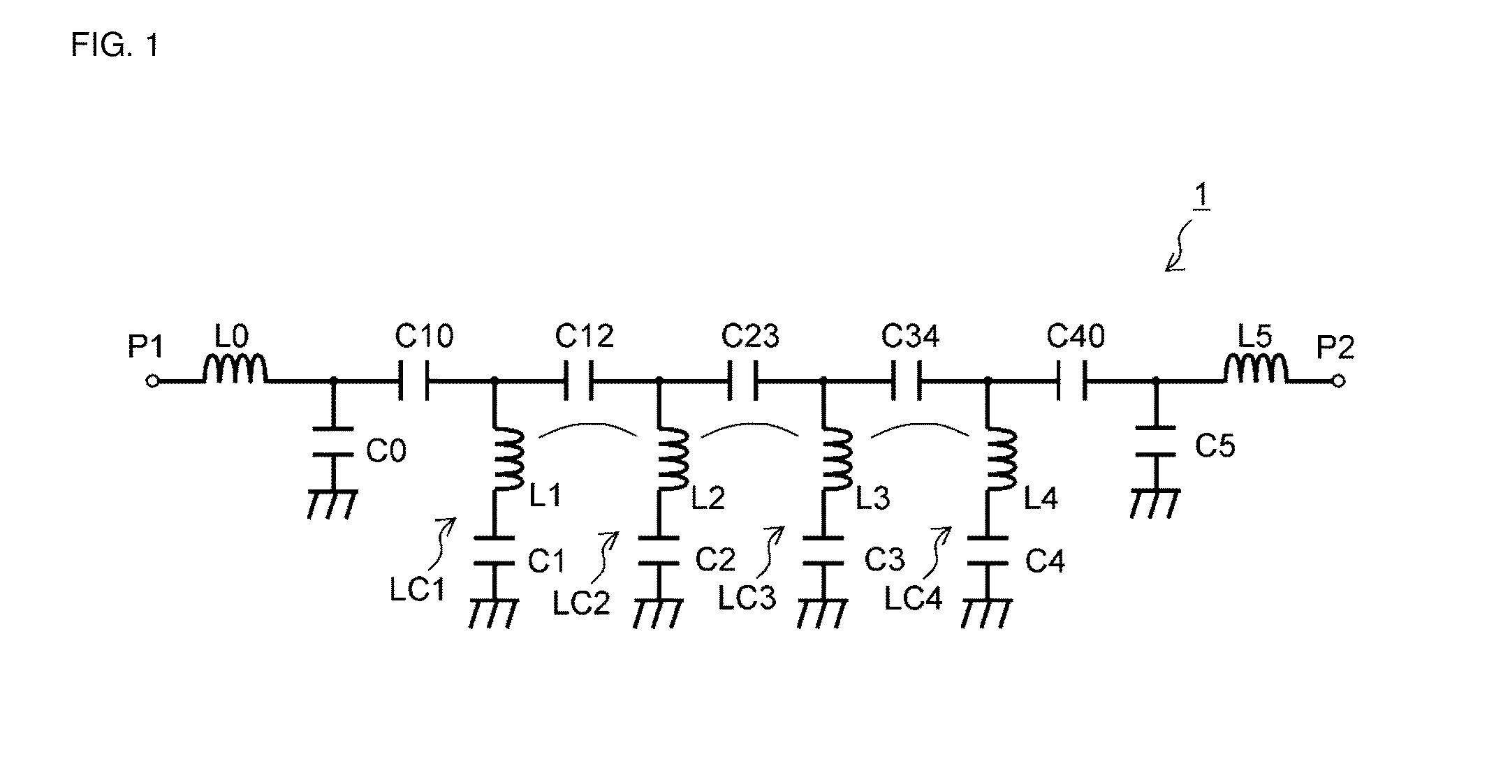
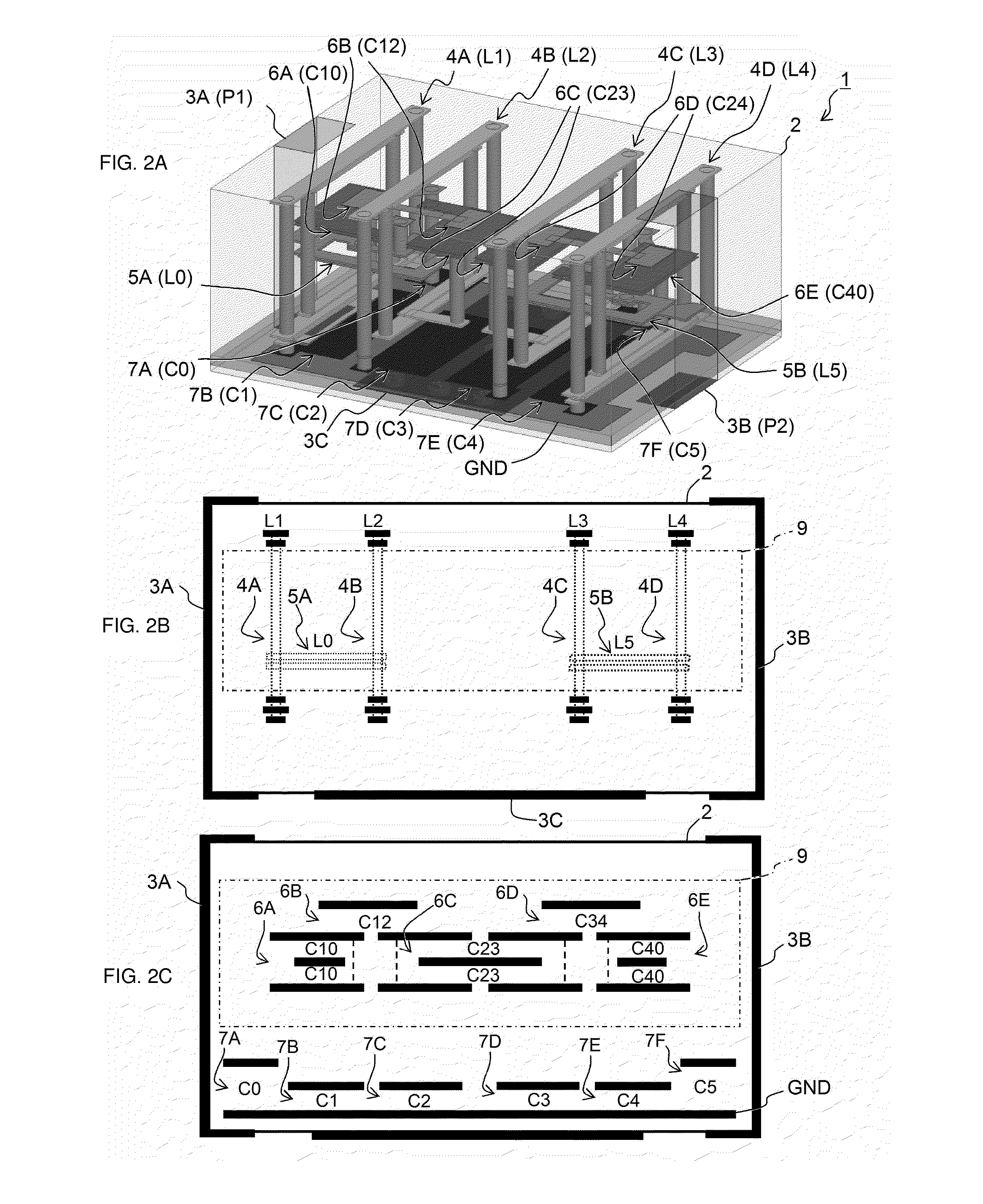
[0034]A high frequency component according to a first preferred embodiment of the present invention is described below. The high frequency component illustrated herein preferably functions as a high pass filter, which has a cutoff frequency band lower than a pass band.

[0035]FIG. 1 is an equivalent circuit diagram of a high frequency component 1 according to the first preferred embodiment. The high frequency component 1 preferably functions as a high pass filter including input and output ports P1 and P2, capacitors C0, C1, C2, C3, C4, C5, C10, C12, C23, C34, and C40, and inductors L0, L1, L2, L3, L4, and L5.

[0036]In the high frequency component 1, the inductor L1 and the capacitor C1 define a serial resonant circuit LC1. Similarly, the inductor L2 and the capacitor C2 define a serial resonant circuit LC2. The inductor L3 and the capacitor C3 define a serial resonant circuit LC3. The inductor L4 and the capacitor C4 define a serial resonant circuit LC4. The capacitor C12 is connected...


PUM


Abstract

A high frequency component includes a multilayer body including a plurality of insulating layers stacked in a stacking direction, linear conductors extending along the insulating layers, interlayer connection conductors extending through at least one of the insulating layers, and planar conductors extending along the insulating layers. The high frequency component further includes transverse coils and internal capacitors. Each of the transverse coils includes the linear conductors and the interlayer connection conductors spirally wound in a plane in a plurality of turns around a winding axis extending in a direction perpendicular or substantially perpendicular to the stacking direction. Each of the internal capacitors includes the planar conductors being opposed to each other such that at least one of the insulating layers is disposed therebetween, the internal capacitor being arranged within a coil opening of the transverse coil when viewed along the winding axis of the transverse coil.

Description

BACKGROUND OF THE INVENTION[0001]1. Field of the Invention[0002]The present invention relates to a high frequency component including an LC circuit disposed in a multilayer body.[0003]2. Description of the Related Art[0004]A component including an LC circuit disposed in a multilayer body is used as a high frequency component. Such a high frequency component including an LC circuit needs to support various frequencies and have a filter characteristic with a steep attenuation pole, and it is necessary to appropriately set the number of stages of resonant circuits that define the LC circuit and the circuit constant of the LC circuit.[0005]When an inductor included in the LC circuit is made of a coil-shaped conductive pattern, the inductance can be increased by increasing the size of the opening of the coil or by increasing in the number of turns of the coil. However, the increase in the size of the opening of the coil or in the number of turns of the coil may lead to an increased size ...

Claims


Application Information

Patent Timeline
Patent Type & Authority Applications(United States)
IPC IPC(8): H03H7/01
CPCH03H7/0161H03H7/0115H01F17/0013H03H7/1758H01F2017/0026H03H2001/0085H03H7/1766H03H7/1775H03H7/09
Inventor WATANABE, KUNIHIRO
Owner MURATA MFG CO LTD
Why Eureka
Try Eureka