Impingement cooling of turbine blades or vanes

Active Publication Date: 2015-01-29
SIEMENS ENERGY GLOBAL GMBH & CO KG
View PDF12 Cites 9 Cited by
  • Summary
  • Abstract
  • Description
  • Claims
  • Application Information

AI Technical Summary

Benefits of technology

[0028]Preferably, the leading piece of the impingement tube is sealed in respect to the at least further cooling chamber. Due to this, the compressor discharge flow entering the leading piece from the side of the platform is unhindered by a contrariwise flow of cooling medium, entering from the leading piece from the side of the at least further platform. The at least further platform covers the leading piece in a hermetically sealed manner, thus saving an additional sealing means. The trailing piece has at its second radial end at the at least further platform an aperture for a flow communication with the at least further cooling chamber. Hence, sufficient cooling medium could be fed to the trailing piece.
[0029]Alternatively, it may be possible, that the leading piece extends in span wise direction at least completely through the at least further cooling chamber from the at least further platform to the at least further cover plate, hence ensuring a sufficient feed of cooling medium into the leading piece. Further, the leading piece of the impingement tube could end both at the cover plate and a

Problems solved by technology

The effect of temperature on the turbine blades and/or stator vanes can be detrimental to the efficient operation of the turbine and can, in extreme circumstances, lead to distortion and possible f

Method used


Image

  • Impingement cooling of turbine blades or vanes
  • Impingement cooling of turbine blades or vanes
  • Impingement cooling of turbine blades or vanes

Examples


Example

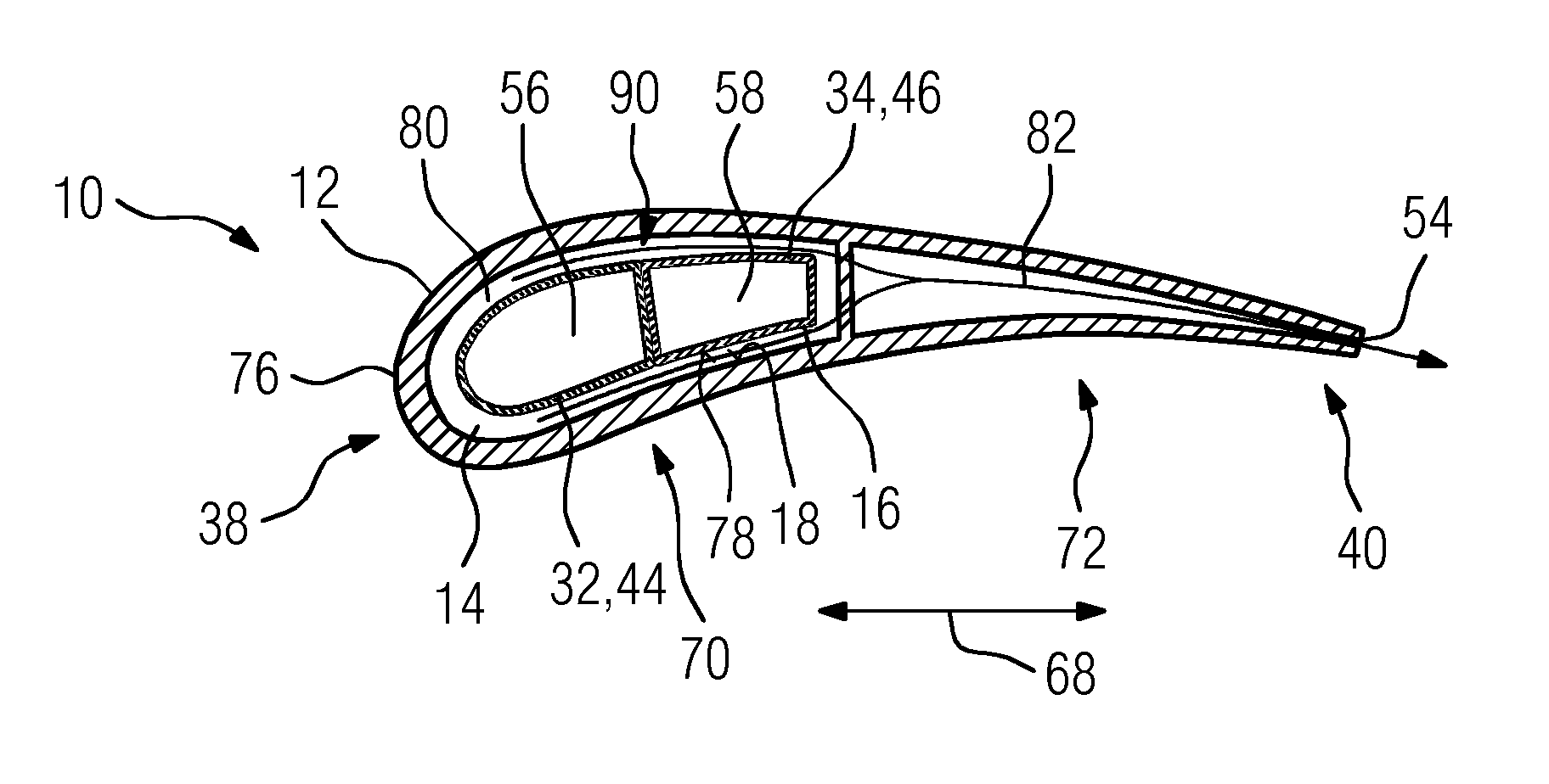
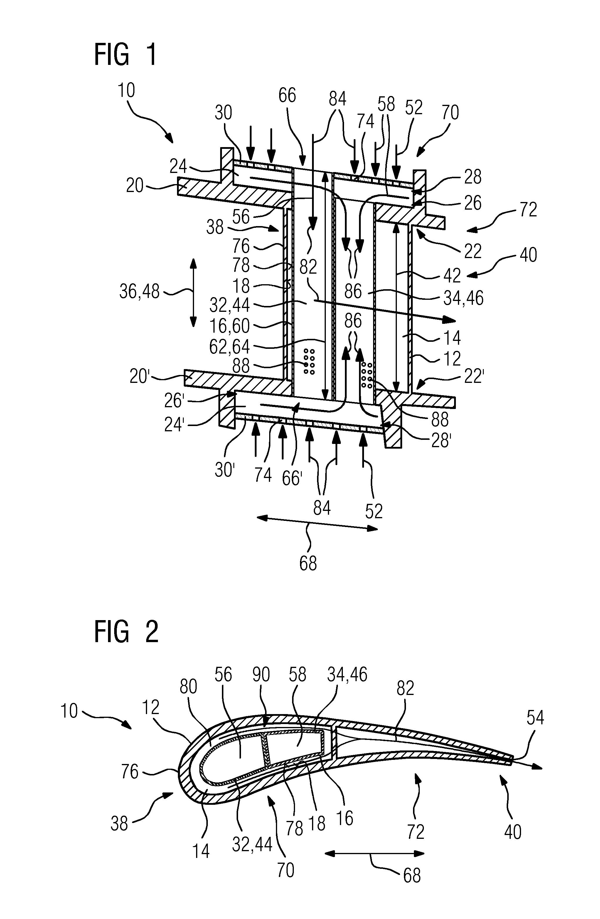
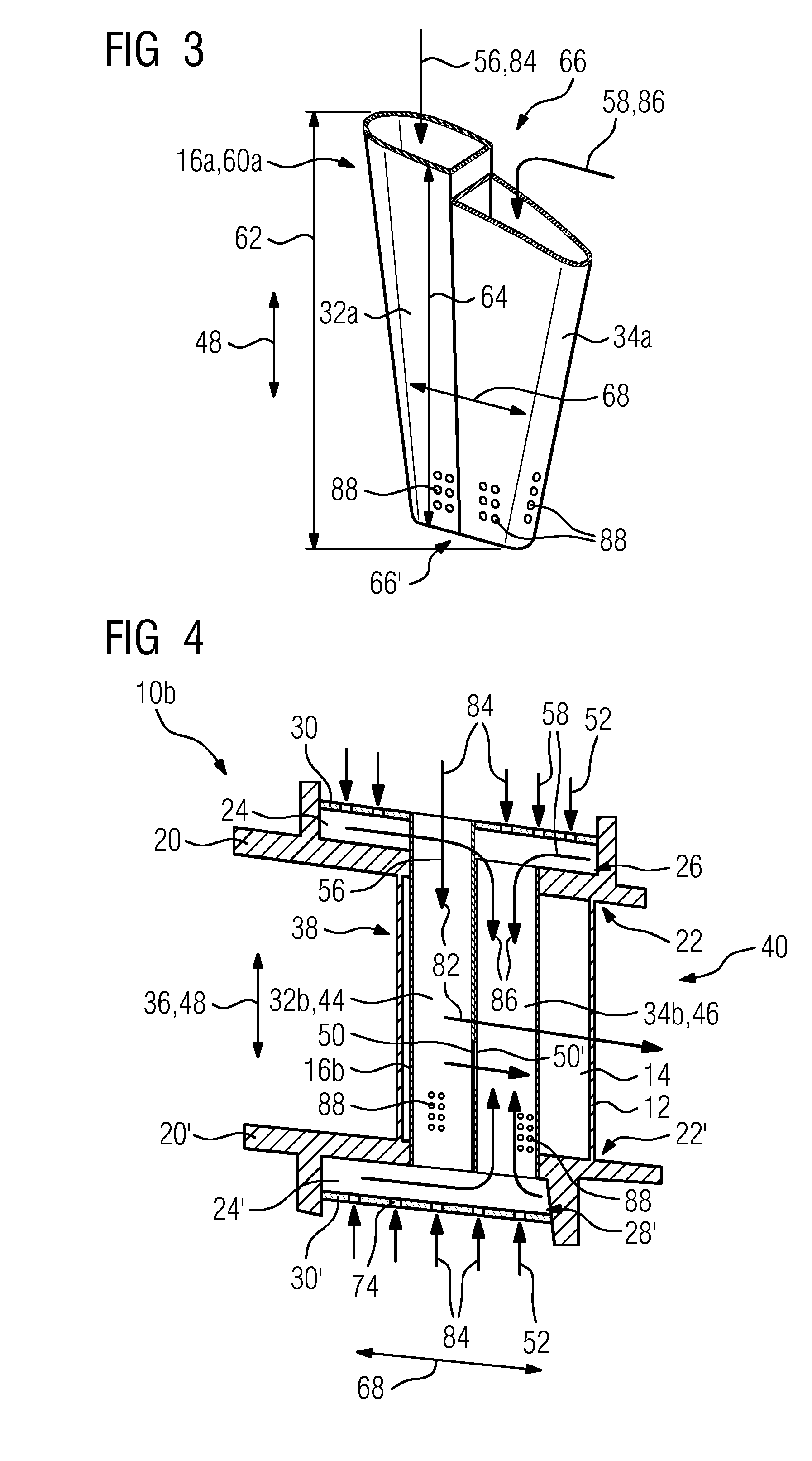
[0048]In the present description, reference will only be made to a vane, for the sake of simplicity, but it is to be understood that the invention is applicable to both blades and vanes of a turbine.

[0049]FIG. 1 shows in a cross section a turbine assembly 10. The turbine assembly 10 comprises a basically hollow aerofoil 12, embodied as a vane, with two cooling regions, specifically, an impingement cooling region 70 and a pin-fin / pedestal cooling region 72. The former is located at a leading edge 38 and the latter at a trailing edge 40 of the aerofoil 12. At two radial ends 22, 22′ of the hollow aerofoil 12, which are arranged opposed towards each other at the aerofoil 12, a platform and a further platform, referred to in the following text as an outer platform 20 and an inner platform 20′, are arranged. The outer platform 20 and the inner platform 20′ are oriented perpendicular to a span wise direction 36 of the hollow aerofoil 12. In a circumferential direction of a not shown turbi...


PUM


Abstract

A turbine assembly is provided having a hollow aerofoil having a cavity with an impingement tube insertable inside the cavity and used for impingement cooling of an inner surface of the cavity, and a platform arranged at a radial end of the hollow aerofoil, and a cooling chamber used for cooling of the platform which is arranged relative to the hollow aerofoil on an opposed side of the platform. The cooling chamber is limited at a first radial end from the platform and at an opposed radial second end from a cover plate. The impingement tube is formed from a leading piece and a trailing piece. The leading piece extends in span wise direction at least completely through the cooling chamber from the platform to the cover plate and the trailing piece terminates in span wise direction at the platform.

Description

CROSS REFERENCE TO RELATED APPLICATIONS[0001]This application is the US National Stage of International Application No. PCT / EP2012 / 073352 filed Nov. 22, 2012, and claims the benefit thereof. The International Application claims the benefit of European Application No. EP12154722 filed Feb. 9, 2012. All of the applications are incorporated by reference herein in their entirety.FIELD OF THE INVENTION[0002]The present invention relates to an aerofoil-shaped turbine assembly such as turbine rotor blades and stator vanes.BACKGROUND TO THE INVENTION[0003]Modern turbines often operate at extremely high temperatures. The effect of temperature on the turbine blades and / or stator vanes can be detrimental to the efficient operation of the turbine and can, in extreme circumstances, lead to distortion and possible failure of the blade or vane. In order to overcome this risk, high temperature turbines may include hollow blades or vanes incorporating so-called impingement tubes for cooling purposes...

Claims


Application Information

Patent Timeline
IPC IPC(8): F01D5/18F01D9/06
CPCF01D9/065F01D5/188F01D5/186F01D5/189F05D2220/31F05D2240/81F05D2260/201F05D2260/205
Inventor MUGGLESTONE, JONATHAN
Owner SIEMENS ENERGY GLOBAL GMBH & CO KG
Why Eureka
Try Eureka