Solder joint structure, power module, power module substrate with heat sink and method of manufacturing the same, and paste for forming solder base layer

a technology of power module and joint structure, which is applied in the direction of manufacturing tools, welding/cutting media/materials, and solventing apparatus, etc., can solve the problems of reducing joint reliability, and achieve the effects of improving joint reliability, and suppressing waviness and wrinkles

Active Publication Date: 2015-02-05
MITSUBISHI MATERIALS CORP
View PDF14 Cites 21 Cited by
  • Summary
  • Abstract
  • Description
  • Claims
  • Application Information

AI Technical Summary

Benefits of technology

[0058]According to the present invention, it is possible to provide a solder joint structure capable of suppressing the occurrence of waviness and wrinkles on the surface of an aluminum member, and improving the joint reliability with a joint member, even at the time of loading the power cycle and the heat cycle; a power module using the solder joint structure, a power module substrate with a heat sink and a manufacturing method thereof.
[0059]In addition, according to the present invention, it is possible to provide a solder base layer forming paste which is disposed and fired on a metal member to thereby react with an oxide film generated on the surface of the metal member and form the solder base layer on the metal member, and which is capable of suppressing the occurrence of waviness and wrinkles on the surface of the metal member even at the time of loading the power cycle and heat cycle by preventing the Ag leaching during soldering.

Problems solved by technology

Further, when the circuit layer or the like is formed of a copper member made of copper or a copper alloy, the melted solder material and copper react and the components of the solder material infiltrates into the inside of the copper member of the circuit layer or the like to alter the characteristics, which is a problem.
When the power cycle and heat cycle are loaded in the power module, there was a possibility that the stress due to the difference in coefficients of thermal expansion of the ceramic substrate and circuit layer (aluminum) acts on the joint interface between the ceramic substrate and the circuit layer, thereby reducing the joint reliability.

Method used


Image

  • Solder joint structure, power module, power module substrate with heat sink and method of manufacturing the same, and paste for forming solder base layer
  • Solder joint structure, power module, power module substrate with heat sink and method of manufacturing the same, and paste for forming solder base layer
  • Solder joint structure, power module, power module substrate with heat sink and method of manufacturing the same, and paste for forming solder base layer

Examples


examples

[0169]The following describes the results of the confirmation experiment conducted in order to confirm the effect of the present invention.

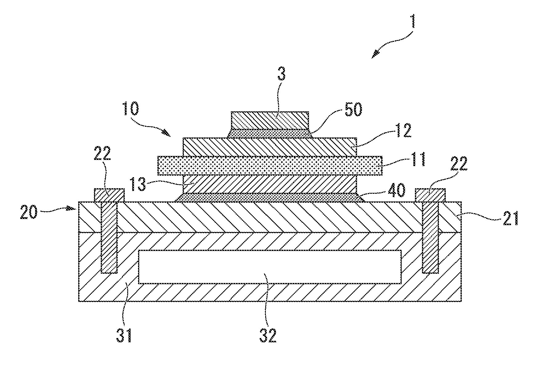
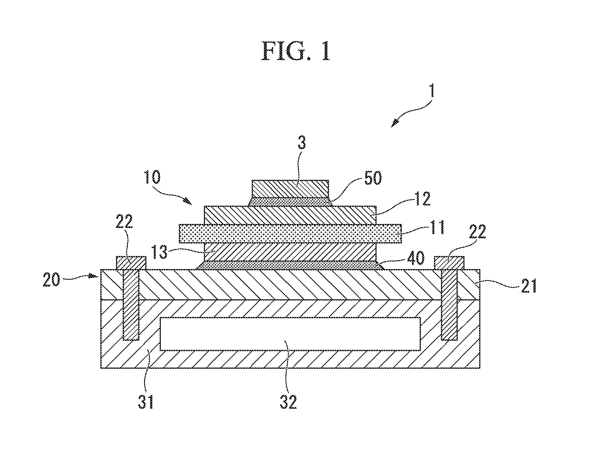
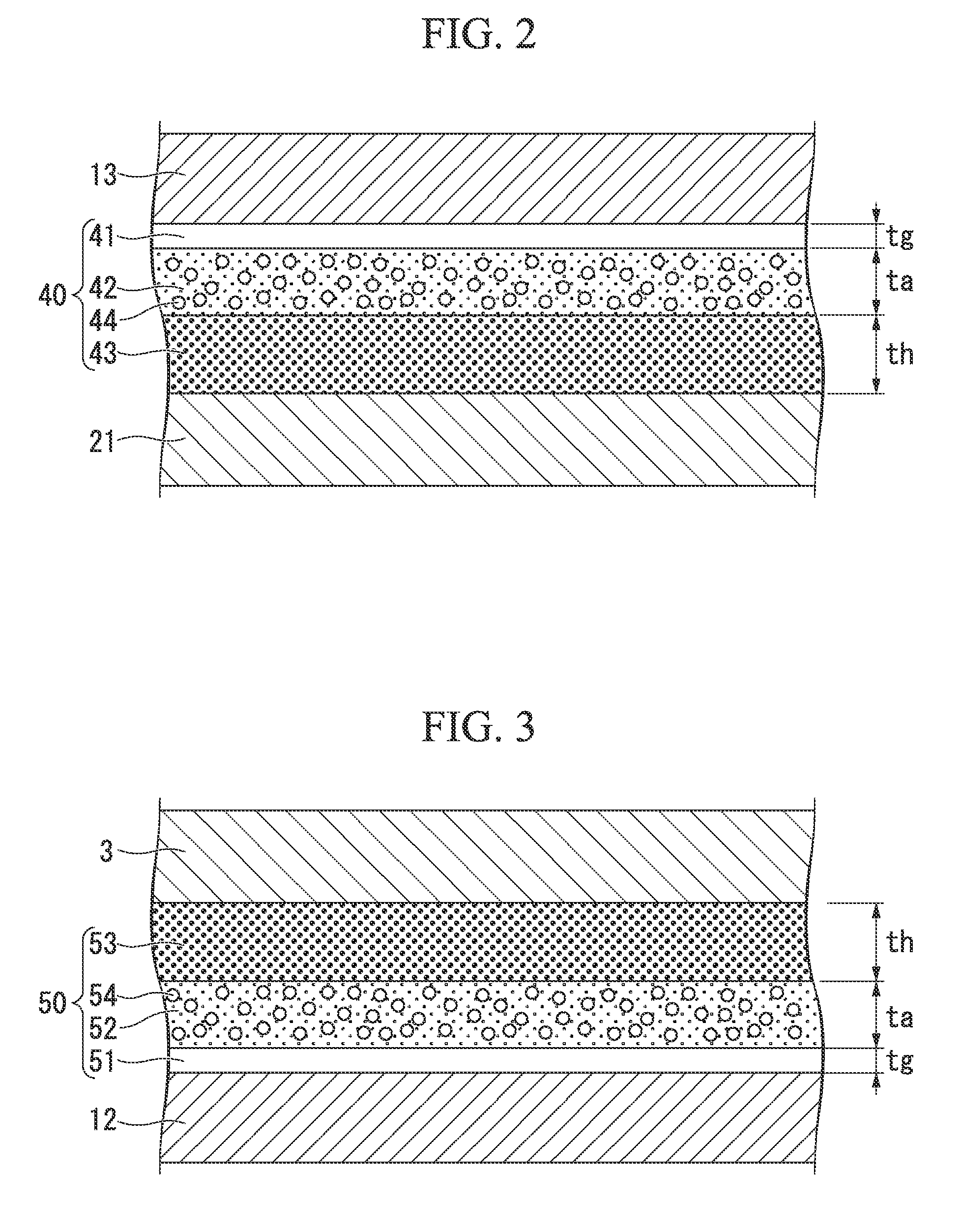
[0170]A fired layer obtained by firing a solder base layer forming paste with the composition shown in Tables 1 and 2 was formed on a circuit layer made of an aluminum plate having a purity of 99.99% or more, and a semiconductor device was joined onto the fired layer in a reducing furnace using Sn—Ag—Cu-based lead-free solder. In Tables 1 and 2, the ratios A / G indicates (weight of silver powder) / (weight of glass powder) and A / O indicates (weight of silver powder) / (weight of crystalline oxide powder), respectively. Note that the coating thickness of the solder base layer forming paste was set to 10 μm. In addition, the firing temperature was set to 575° C., and the firing time was set to 10 minutes. As a result, an Ag fired layer (solder base layer) in which a thickness of the fired layer was about 8 μm and a thickness of the glass layer was about...


PUM

PropertyMeasurementUnit
softening temperatureaaaaaaaaaa
particle sizeaaaaaaaaaa

Abstract

There are provided a solder joint structure, a power module using the joint structure, a power module substrate with a heat sink and a method of manufacturing the same, as well as a solder base layer forming paste which is disposed and fired on a metal member to thereby react with an oxide film generated on the surface of the metal member and form the solder base layer on the metal member, capable of suppressing the occurrence of waviness and wrinkles on the surface of the metal member even at the time of loading the power cycle and heat cycle and improving the joint reliability with a joint member.

Description

TECHNICAL FIELD[0001]The present invention relates to a solder joint structure obtained by soldering an aluminum member made of aluminum or an aluminum alloy and a joint member using a solder material; a power module using the solder joint structure; a power module substrate with a heat sink and a method of manufacturing the same; and a solder base layer forming paste that forms a solder base layer on a metal member by being disposed and fired on the metal member.[0002]Priority is claimed on Japanese Patent Application No. 2012-029646, filed Feb. 14, 2012, and Japanese Patent Application No. 2012-029683, filed Feb. 14, 2012, the contents of which are incorporated herein by reference.BACKGROUND ART[0003]As a solder joint structure formed by soldering a metal member and a joint member using a solder material, for example, the power module as shown in Patent Documents 1 and 2 can be exemplified.[0004]The power module is provided with a power module substrate formed by soldering a metal...

Claims


Application Information

Patent Timeline
Patent Type & Authority Applications(United States)
IPC IPC(8): H01L23/00B23K1/19B23K1/20H01L23/367
CPCH01L24/33H01L2924/0105H01L24/83B23K1/19B23K1/203H01L2224/32225H01L2224/8384H01L2224/29339H01L2224/32245H01L2224/83801H01L2924/01013H01L2924/014H01L2924/1306H01L2924/13055H01L2924/05432H01L2924/01028H01L23/367H01L23/3735H01L24/32B23K1/0016B23K35/3006B23K35/3602B23K35/0244B23K35/30B23K35/36B23K35/3607B23K35/0222B23K35/025B23K35/0272H01L2924/1305H01L2924/351H01L2924/15787H01L2224/29324H01L2224/29299H01L2224/29239H01L24/29H01L2224/03505H01L2224/04026H01L2224/27505H01L2224/29005H01L2224/29083H01L2224/29111H01L2224/29386H01L2224/83192H01L2224/8321H01L2224/29286H01L2224/83539H01L2224/83686H01L2924/12042H01L2924/00014H01L2924/00H01L2924/01047H01L2924/01029H01L2924/01051H01L2924/01049H01L2924/207H01L2924/05341H01L2924/05442H01L2924/053H01L2924/206
Inventor NISHIMOTO, SHUJINISHIKAWA, KIMIHITONAGATOMO, YOSHIYUKI
Owner MITSUBISHI MATERIALS CORP
Why Eureka
Try Eureka