
Sensing pm electrical machine position

a technology of electrical machines and sensing devices, applied in the field of electrical machines, can solve the problems of not being attractive in applications such as aerospace or ground vehicles, and the above-mentioned techniques may not guarantee good accuracy in rotor position estimation at zero and low speed

Active Publication Date: 2015-02-05
HAMILTON SUNDSTRAND CORP
View PDF27 Cites 7 Cited by
  • Summary
  • Abstract
  • Description
  • Claims
  • Application Information

AI Technical Summary

Benefits of technology

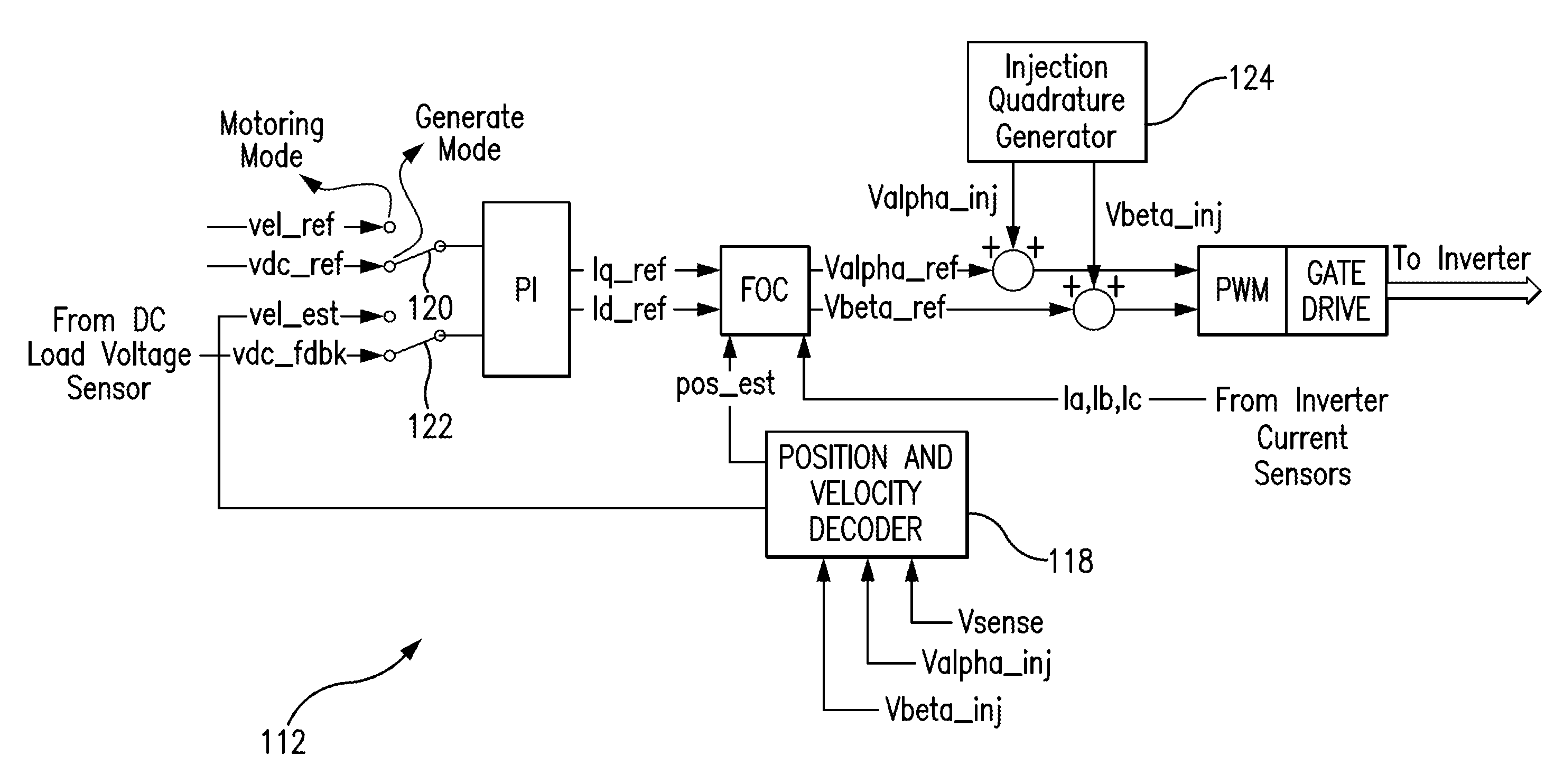
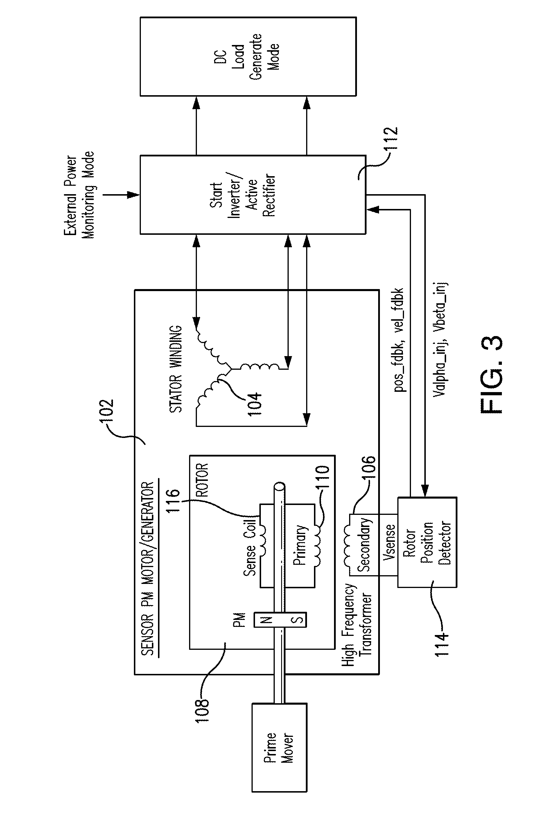
The patent describes an electrical machine with a stator and rotor, and a system for controlling it. The system includes a primary transformer coil and a secondary transformer coil, with a plurality of embedded permanent magnets on the rotor. A primary transformer coil is wound on the stator and is operatively connected to form a rotating transformer with the secondary transformer coil. An inverter / active rectifier component is operatively connected to the stator winding and the secondary transformer coil to control the stator winding based on a sense signal from the secondary transformer coil. A rotor position detector is operatively connected to the inverter / active rectifier component to receive injection signals and output position and velocity feedback signals. The inverter / active rectifier component includes a position and velocity decoder and a synchronous filter to receive the sense signal and the injection signals and output the filtered sense signal. The position / velocity estimator includes a first zero cross detector and a second zero cross detector to receive the filtered sense signal and output the position feedback signal. The system allows for accurate position and velocity estimation and control of the electrical machine.

Problems solved by technology

The above techniques may not guarantee good accuracy in rotor position estimation at zero and low speed.
However, for the larger size PM machines this approach considerably penalizes the power density of the machine, and, therefore, may not be attractive in applications such as aerospace or ground vehicles.
However, there is still a need in the art for systems and methods that allow for improved performance such as reliability, complexity, and cost.

Method used


Image

  • Sensing pm electrical machine position
  • Sensing pm electrical machine position
  • Sensing pm electrical machine position

Examples


Embodiment Construction

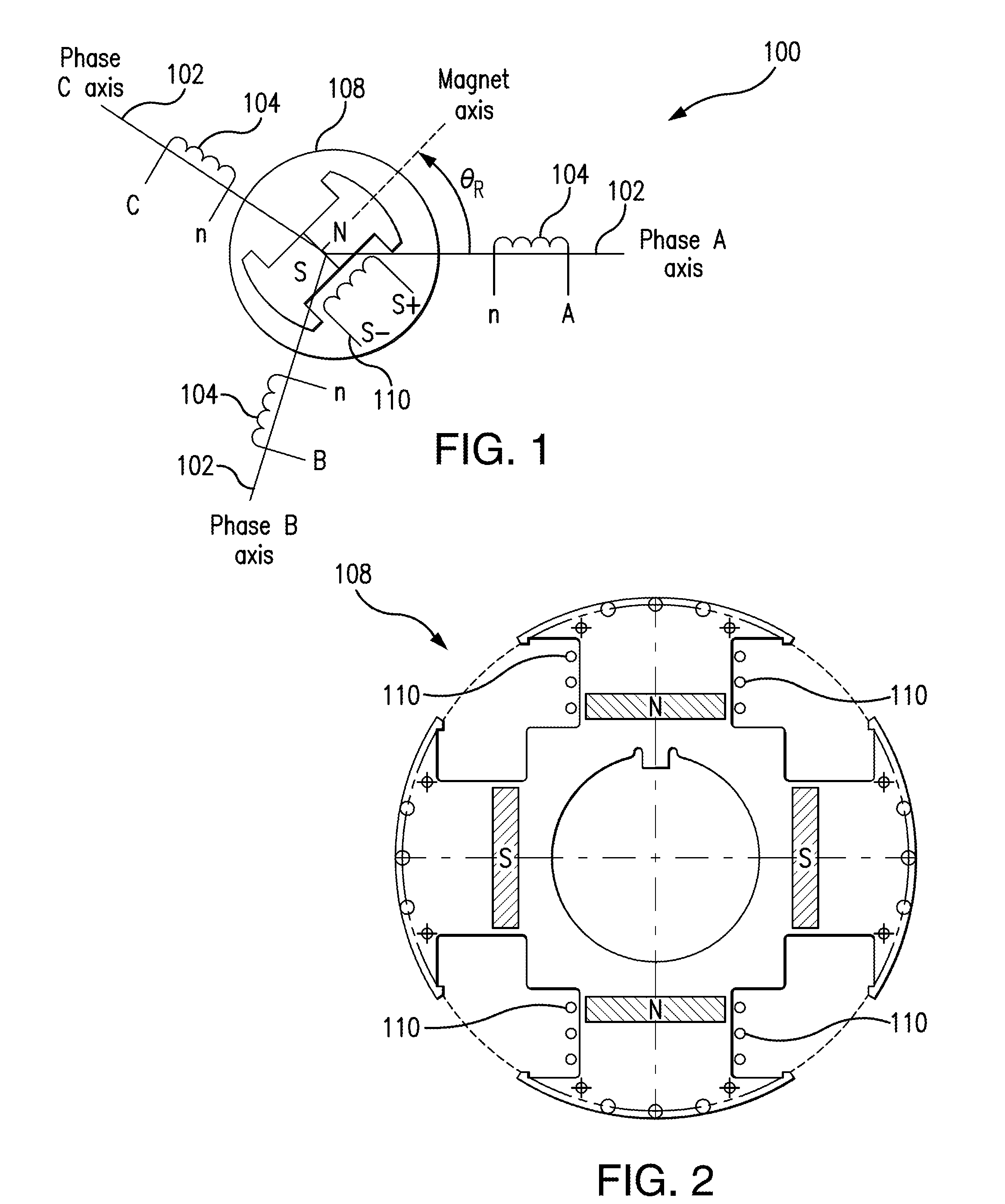
[0027]Reference will now be made to the drawings wherein like reference numerals identify similar structural features or aspects of the subject disclosure. For purposes of explanation and illustration, and not limitation, a partial view of an exemplary embodiment of an electrical machine is shown in FIG. 1 and is designated generally by reference character 100. Other embodiments of electrical machines, or aspects thereof, are provided in FIGS. 2-7, as will be described. The systems and methods disclosed herein can be used, for example, to completely eliminate the resolver as a position sensor for electric engine start and active rectification commutation to improve system reliability, complexity, and cost without necessarily reducing power density.

[0028]FIG. 1 is a sensor PM electrical machine diagram showing a sense winding wired around two or more rotor poles. The excitation coil is a primary winding of a single phase high frequency rotating transformer (HFRT). Electrical machine ...


PUM


Abstract

An electrical machine includes a stator having a stator winding and a secondary transformer coil. A rotor is operatively connected to rotate relative to the stator, wherein the rotor includes a plurality of embedded permanent magnets. A primary transformer coil is wound on the rotor and is operatively connected to form a rotating transformer with the secondary transformer coil. An inverter / active rectifier component is operatively connected to the stator winding and the secondary transformer coil to control the stator winding based on a sense in the secondary transformer coil received from the primary transformer coil.

Description

BACKGROUND OF THE INVENTION[0001]1. Field of the Invention[0002]The present disclosure relates to electrical machines such as motors and generators, and more particularly to angular position and velocity estimation of permanent magnet (PM) synchronous machines.[0003]2. Description of Related Art[0004]PM machines can be classified based on the flux distribution or back-electromagnetic force (EMF) waveform as square-wave brushless DC machines (BLDCM) and sine-wave or synchronous machines (PMSM). The BLDCM utilizes a trapezoidal back-EMF waveform supplied by rectangular current waveforms with conduction duration of 120°. The commutation is based on the rotor position with 60° resolution typically provided by Hall sensors. The PMSM utilizes sinusoidal back-EMF supplied by sinusoidal current waveforms properly phased with respect to the back-EMF. The rotor position information is typically provided by resolvers or encoders.[0005]Most of sensorless motor controllers utilize position estim...

Claims


Application Information

Patent Timeline
IPC IPC(8): H02K11/00H02P9/00H02P6/16
CPCH02K11/0031H02P9/009H02P6/16H02K11/001H02P6/183H02K11/20H02K11/225
Inventor ROZMAN, GREGORY I.GIERAS, JACEK F.MOSS, STEVEN J.
Owner HAMILTON SUNDSTRAND CORP
Learn More