Compact structure of power-supply apparatus capable of minimizing electromagnetic noise

a compact structure and power supply technology, applied in the direction of power conversion systems, dc-dc conversion, instruments, etc., can solve the problems of increasing the overall length of the wire connecting the electronic parts together, increasing the overall size of the power supply apparatus, and reducing so as to reduce the loss of electric energy, reduce the overall length, and reduce the distance between the parts

Active Publication Date: 2015-02-05
DENSO CORP
View PDF6 Cites 4 Cited by
  • Summary
  • Abstract
  • Description
  • Claims
  • Application Information

AI Technical Summary

Benefits of technology

[0010]It is therefore an object to provide an improved structure of a power-supply apparatus which is capable of being reduced in size and designed to reduce electromagnetic noise to enhance the efficiency in operation thereof.
[0012]Specifically, one of the transformer and the secondary electronic device is laid on the primary semiconductor unit to make the first stack. Similarly, the other of the transformer and the secondary electronic device is laid on the secondary semiconductor unit to make the second stack. This permits the power-supply apparatus to be reduced in overall size thereof and minimizes adverse effects of electromagnetic noise to ensure the high efficiency in power supply operation.
[0013]In other words, each of the first stack and the second stack is made up of two parts laid to overlap each other, thereby decreasing an area to which the parts of the power-supply apparatus are projected, as viewed in a direction in which the two parts are laid on each other, which allows the power-supply apparatus to be reduced in size thereof.
[0015]The parts of each of the first stack and the second stack are, as described above, laid on each other, thus resulting in a minimized distance between the parts. This permits the connecting conductors to be decreased in overall length thereof, which reduces the loss of electric energy therefrom and also decreases the volume of space consumed by the connecting conductors in the power-supply apparatus. The decrease in overall length of the connecting conductors will result in a decrease in loop area of the connecting conductors, which reduces the electromagnetic noise arising from the connecting conductors.

Problems solved by technology

This results in an increased overall size of the power-supply apparatus.
The electronic parts are placed on the same level or horizontally, thus needing to secure an interval between adjacent ones of the electronic parts, which leads to an increase in overall length of wire connecting the electronic parts together.
Such an increase will result in an increase in electric resistance of the wire, thus causing a loss of electric energy.
This lowers the efficiency in operation of the power-supply apparatus.
The increase in overall length of the wire will also result in an increase in loop area of the wire, thereby increasing the possibility of electromagnetic noise.
A part of the electromagnetic noise emitted from the wiring board on which the electronic parts are mounted toward the base plate is blocked by the base plate, while the other part of the electromagnetic noise radiating away from the wiring board may affect operations of peripheral devices.

Method used


Image

  • Compact structure of power-supply apparatus capable of minimizing electromagnetic noise
  • Compact structure of power-supply apparatus capable of minimizing electromagnetic noise
  • Compact structure of power-supply apparatus capable of minimizing electromagnetic noise

Examples


first embodiment

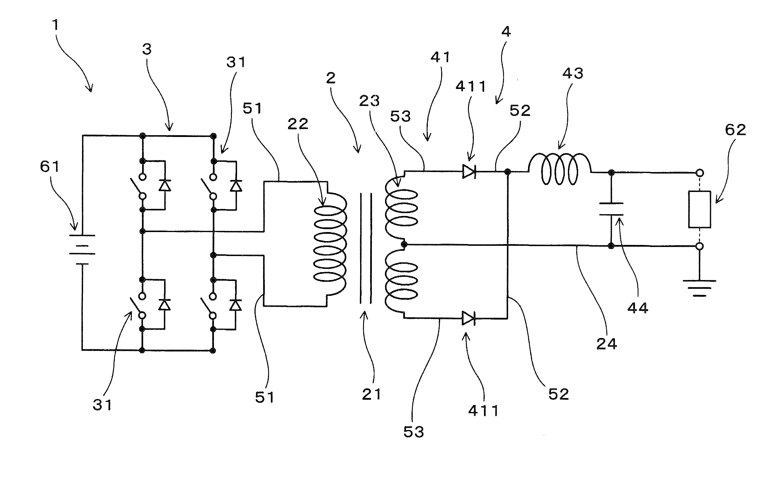
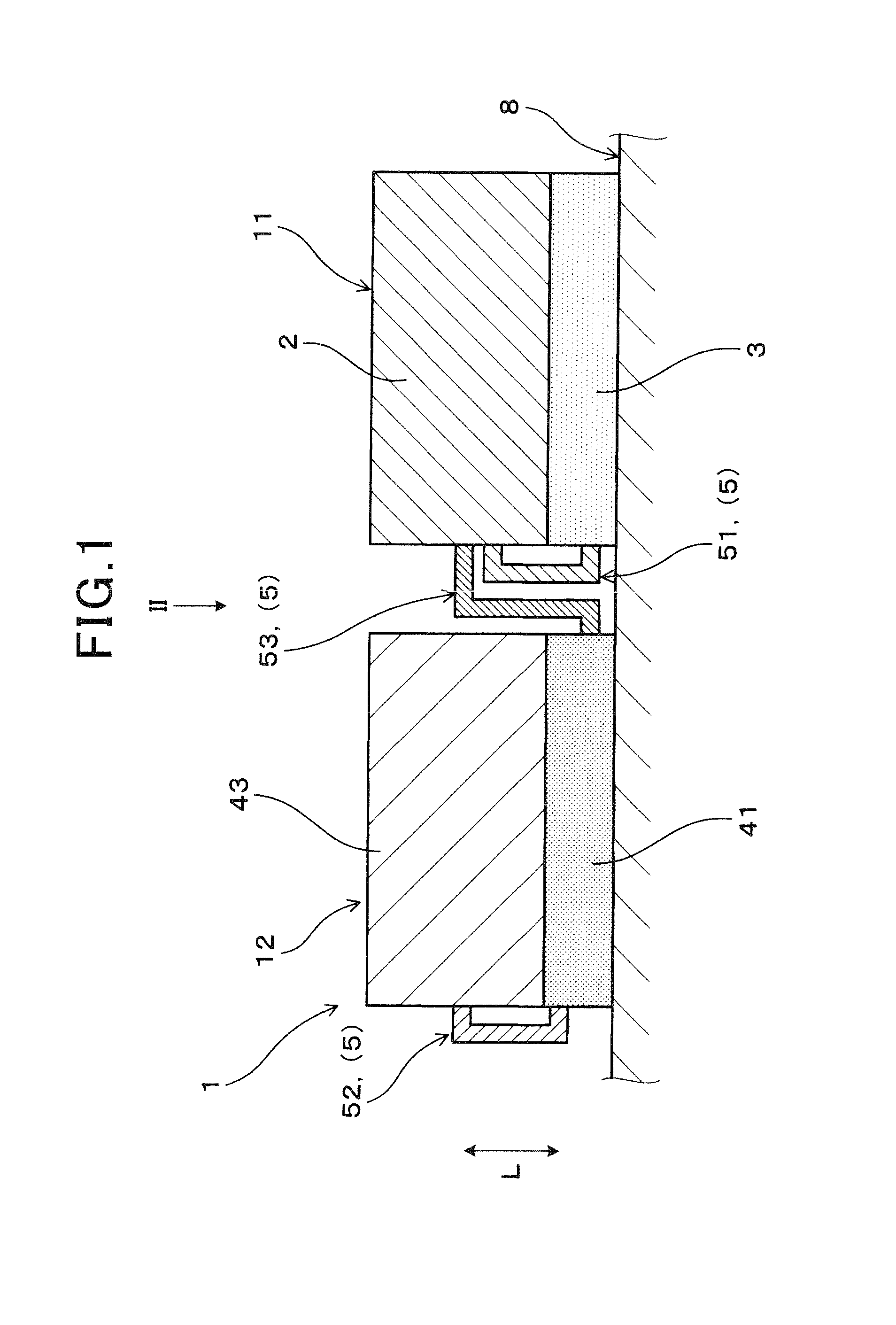
[0037]Referring to the drawings, wherein like reference numbers refer to like parts in several views, particularly to FIGS. 1 to 3, there is shown a power-supply apparatus 1 according to the The power-supply apparatus 1 includes a transformer 2, a primary semiconductor module 3, a secondary semiconductor module 41, and a choke coil 43. The transformer 2 is equipped with a primary coil 22 and two secondary coils 23. The primary semiconductor module 3 and the secondary semiconductor module 41 work as a primary semiconductor unit and a secondary semiconductor unit, respectively. The choke coil 43 also works as a secondary semiconductor device which makes up a secondary circuit 4 along with the secondary semiconductor module 41.

[0038]The primary semiconductor module 3 connects with the primary coil 22 of the transformer 2. The secondary semiconductor module 41 connects with the secondary coils 23 of the transformer 2. Each of the primary semiconductor module 3 and the secondary semicon...

fourth embodiment

[0078]The power-supply apparatus 1 of this embodiment, as illustrated in FIGS. 10 to 13, has the same circuit structure as that in the

[0079]The other arrangements and beneficial effects are identical with those in the first embodiment, and explanation thereof in detail will be omitted here.

[0080]FIGS. 14 and 15 illustrate the power-supply apparatus 1 according to the sixth embodiment which is partially different in structure from the first embodiment. The same reference numbers as employed in the first embodiment will refer to the same parts, and explanation thereof in detail will be omitted here.

[0081]The power-supply apparatus 1 is equipped with a conductive member 81 and a grounding conductor 24. The conductive member 81 is joined to the base plate 8. The grounding conductor 24 connects between the conductive member 81 and the transformer 2. The base plate 8 is connected to ground, so that the electric potential thereat is 0V.

[0082]The conductive member 81 is made of conductive m...

sixth embodiment

[0090]The conductive member 81 has the conductive plate 812 placed in direct contact with the upper surfaces of the first stack 11 and the second stack 12. Other arrangements are identical with those in the

[0091]Specifically, the conductive plate 812 works as a heat radiator to absorb heat, as developed in the first stack 11 and the second stack 12. The conductive plate 812 also dissipates the absorbed heat and thus serves as a cooler to cool the first stack 11 and the second stack 12 to keep them at a desired temperature.

[0092]The structure of the power-supply apparatus 1 of this embodiment offers substantially the same beneficial advantages as those in the first embodiment.

[0093]It is advisable that the conductive plate 812 be made of material which is a highly electrically conductive and / or highly thermally conductive material.

[0094]The power-supply apparatus 1 may also have highly thermally conductive members disposed between the conductive plate 812 and the first stack 11 and b...


PUM


Abstract

A power-supply apparatus is provided which includes a transformer, a primary semiconductor unit, a secondary semiconductor unit, and a secondary electronic device. Each of the primary semiconductor unit and the secondary semiconductor units has a plurality of semiconductor devices installed therein. The transformer, the primary semiconductor unit, the secondary semiconductor unit, and the secondary electronic device are electrically joined through connecting conductors. The transformer is laid on the primary semiconductor unit to make a first stack. Similarly, the secondary electronic device is laid on the secondary semiconductor unit. This permits the power-supply apparatus to be reduced in overall size thereof and minimizes adverse effects of electromagnetic noise to ensure the high efficiency in power supply operation.

Description

CROSS REFERENCE TO RELATED DOCUMENT[0001]The present application claims the benefit of priority of Japanese Patent Application No. 2013-157751 filed on Jul. 30, 2013 and Japanese Patent Application No. 2014-72806 filed on Mar. 31, 2014, disclosures of which are incorporated herein by reference.BACKGROUND OF THE INVENTION[0002]1. Technical Field[0003]This disclosure relates generally to a power-supply apparatus which is compact in structure and capable of minimizing adverse effects of electromagnetic noise.[0004]2. Background Art[0005]Hybrid vehicles or electric vehicles usually employ a power-supply apparatus such as a DC-DC converter or a battery charger equipped with a DC-DC converter. Japanese Patent First Publication No. 2000-14149 discloses such a type of power-supply apparatus which is equipped with electronic parts such as semiconductor devices in which switches are fabricated, a choke, and a transformer. The electronic parts are fabricated on a mounting surface of a wiring b...

Claims


Application Information

Patent Timeline
Patent Type & Authority Applications(United States)
IPC IPC(8): H02M1/44H02M3/24
CPCH02M3/24H02M1/44H01F27/06H02M3/28
Inventor HANDA, YUUICHIMISAWA, KATSUTOYOTAKEMOTO, YUUKIYAMASAKI, SHOTAROKURAUCHI, SHUJI
Owner DENSO CORP
Why Eureka
Try Eureka