
Application of Dielectric Layer and Circuit Traces on Heat Sink

a dielectric layer and circuit tracing technology, applied in the direction of resistive material coating, surface pretreatment, synthetic resin layered products, etc., can solve the problems of reducing the life of the led, implementing energy-saving leds, and reducing the light output, so as to increase the overall heat transfer of the board, increase the thermal conductivity, and high performance

Inactive Publication Date: 2015-02-12
PEN
View PDF2 Cites 9 Cited by
  • Summary
  • Abstract
  • Description
  • Claims
  • Application Information

AI Technical Summary

Benefits of technology

The patent text discusses the problem of LED chips generating too much heat and the importance of efficiently managing the heat to maintain proper operation. The text describes various approaches to thermal management, such as reducing the number of thermally resistant layers and using metal substrates with high thermal conductivity to increase heat loss. However, the challenge still remains to integrate these heat management techniques into LED lighting designs while keeping the cost down. The patent also mentions the use of FR4 circuit boards with high thermal conductivity aluminum backplanes and copper conduction layers to improve heat dissipation. The thermal conductivity of the adhesives used to bond the circuit boards to the aluminum substrate and the low thermal conductivity of the adhesives used to bond the circuit boards to copper substrates are also discussed.

Problems solved by technology

A primary obstacle to readily implement energy-saving LED (“light emitting diode”) lighting systems in established commercial and municipal lighting networks lies in dealing with the heat that is generated by high-power LEDs, which are required to produce sufficient light output needed in commercial luminaries.
Rises in junction, temperature in the LED result in color-shifted, reduced-light output, and ultimately reduced life of the LED.
Of course, a significant problem with such an arrangement is that heat is not as efficiently transferred from the LEDs to the circuit boards to the heat sink parts.
When the MCPCB is mounted to a heat sink, there are multiple interfaces incorporated in the structure that contribute to poor thermal transfer between the layers.
In the case of a mechanical fastener or bolt-on mounting, mismatched surface roughness of the heat sink and MCPCB create micro-sized air gaps between the boards.
Phonon propagation across the interlace of two dissimilar materials is often poor, resulting in a overall low thermal conductivity.

Method used


Image

  • Application of Dielectric Layer and Circuit Traces on Heat Sink
  • Application of Dielectric Layer and Circuit Traces on Heat Sink
  • Application of Dielectric Layer and Circuit Traces on Heat Sink

Examples


Embodiment Construction

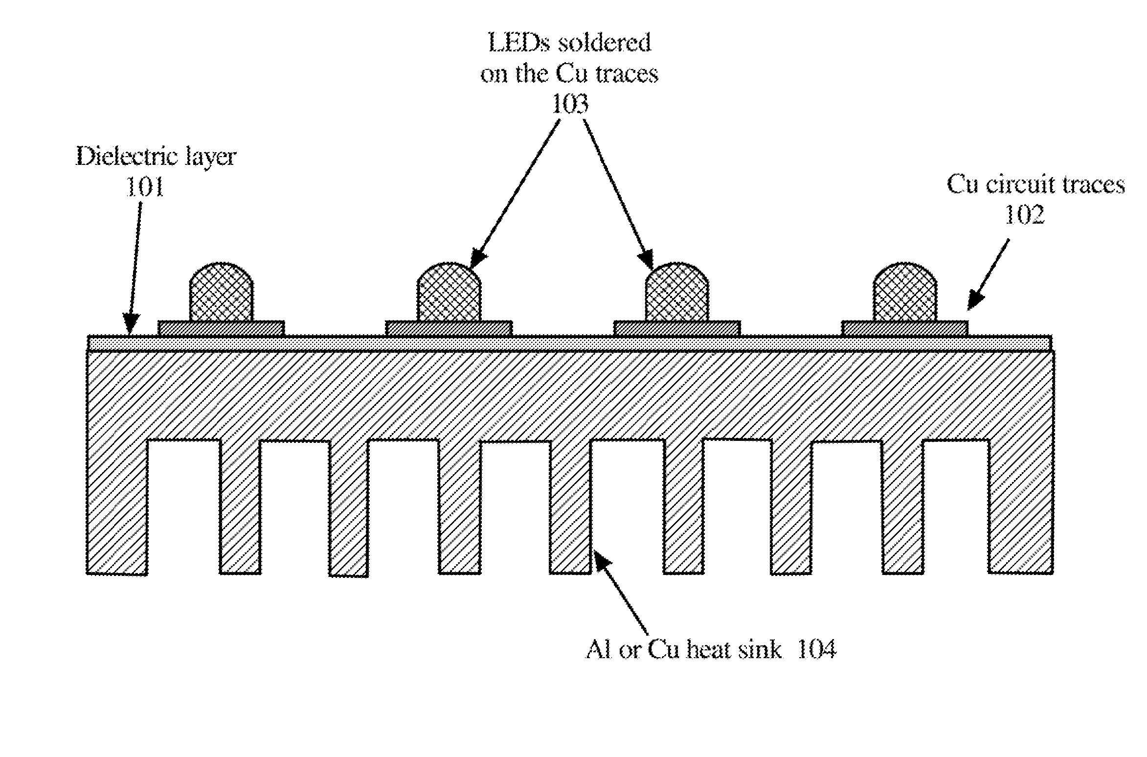
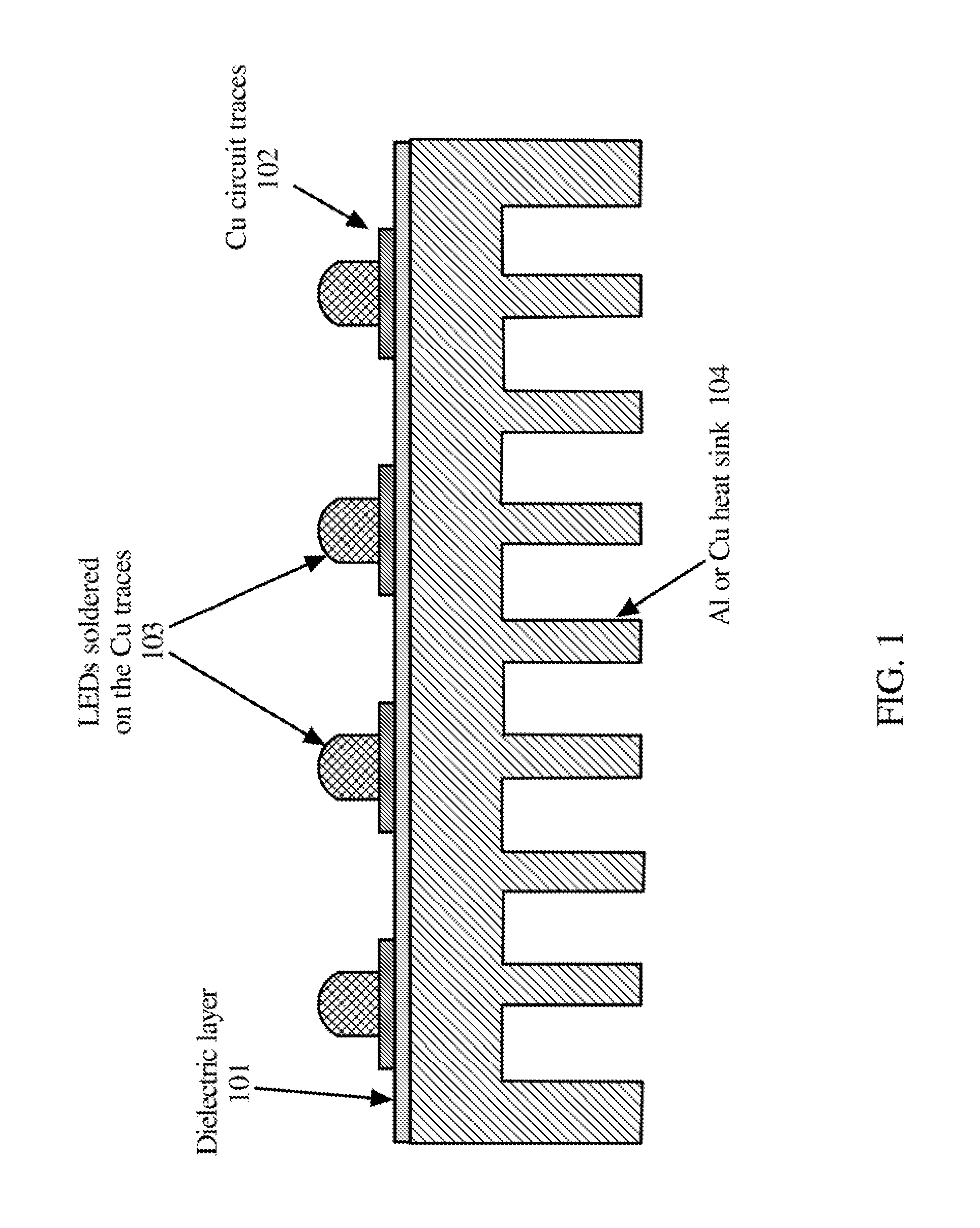
[0023]Referring to FIG. 1, embodiments of the present invention directly apply the dielectric layer 101 and Cu circuit traces 102 on the Al or Cu heat sink parts 104 so that one can eliminate the use of separately manufactured LED circuit boards. A process for making embodiments of the present invention may first start with a preparation of the surface of the heat sink part 104 such as polishing such a surface. The dielectric layer 101 is directly applied onto the surface of the heat sink part 104, such as in accordance with the various examples described herein. For example, the composition for making the dielectric layer may be made into a paste or ink and then printed as a paste or ink, or applied with some other equivalent method for applying a paste or ink. Or, a lamination process may be utilized, as further described herein. The electrical circuit traces are then applied (e.g., printed as an ink or paste, lithographically patterned) onto the dielectric layer 101 in the requir...


PUM

PropertyMeasurementUnit
densityaaaaaaaaaa
thicknessaaaaaaaaaa
thicknessaaaaaaaaaa

Abstract

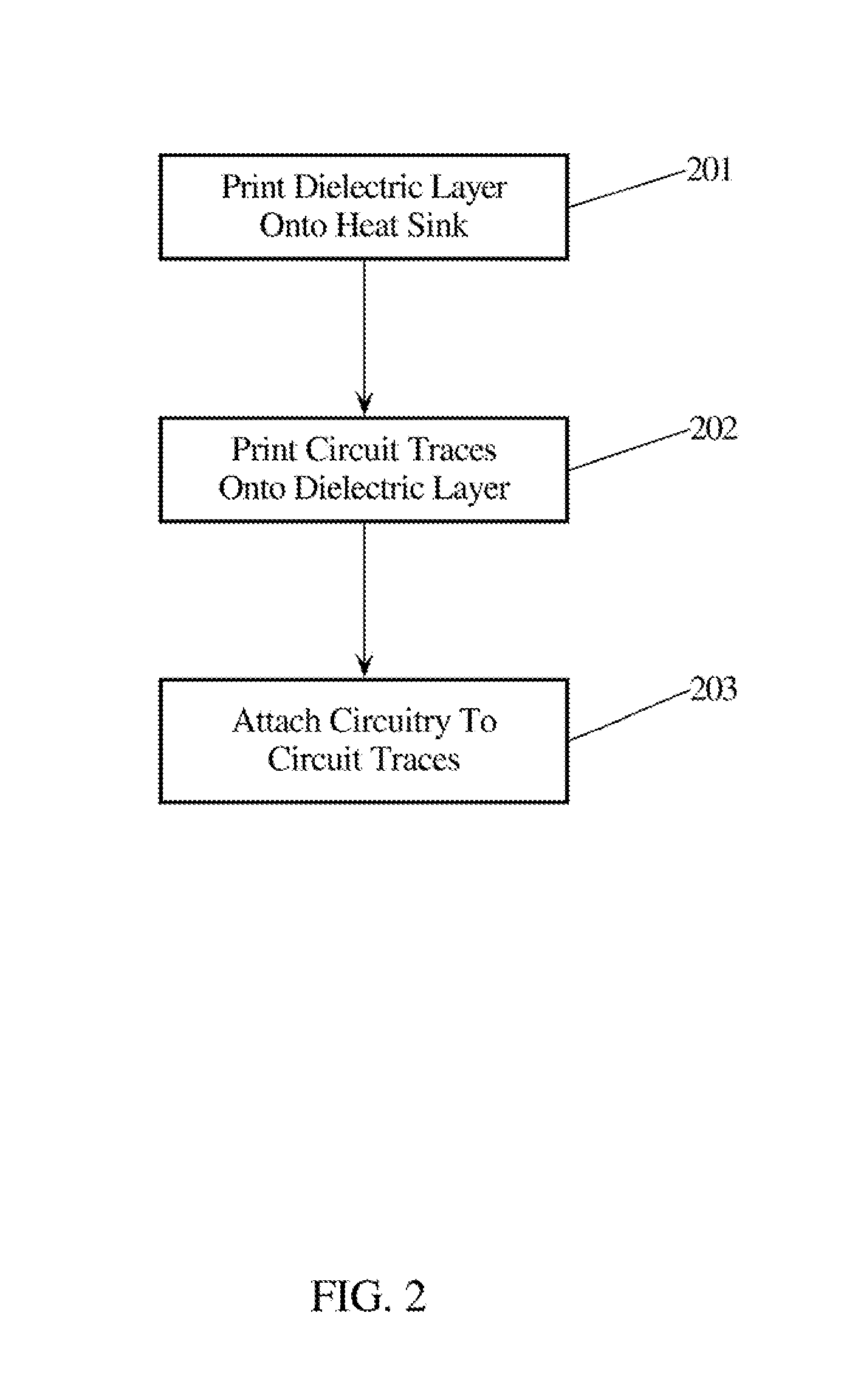
A dielectric layer is directly applied onto the surface of a heat sink part. For example, the composition for making the dielectric layer may be made into a paste or ink and then printed as a paste or ink, or applied with some other equivalent method, such as a lamination technique. The electrical circuit traces are then printed in a similar fashion onto the dielectric layer in the required pattern for whatever circuitry is to be applied. That circuitry (e.g., circuit elements) is then attached to the electrical traces as needed for the particular application.

Description

[0001]This application claims priority to U.S. Provisional Patent Applications Ser. Nos. 61 / 613,254 and 61 / 613,342, which are hereby Incorporated by reference herein.TECHNICAL FIELD[0002]The present invention, relates in general to thermal management composite films, and in particular, to a thermal management composite film on which electrical circuits can be directly printed.BACKGROUND AND SUMMARY[0003]A primary obstacle to readily implement energy-saving LED (“light emitting diode”) lighting systems in established commercial and municipal lighting networks lies in dealing with the heat that is generated by high-power LEDs, which are required to produce sufficient light output needed in commercial luminaries. State of the art LEDs can consume in excess of 10 watts each, and even at the efficiency levels of today's LEDs, the majority of that power is being converted to heat as a byproduct of the light generated in the semiconductor junction of the device.[0004]This heat is internall...

Claims


Application Information

Patent Timeline
Patent Type & Authority Applications(United States)
IPC IPC(8): H05K3/00H05K3/06F21K99/00H05K3/44H05K3/46H05K3/12H05K3/34
CPCH05K3/0061H05K3/12H05K3/06H05K3/34F21Y2101/02H05K3/4655F21K9/90H05K2201/10106H05K3/44H05K1/056H05K2201/0209F21Y2115/10Y10T29/4913
Inventor JIANG, NANYANIV, ZVINOVAK, JAMES P.LI, XUEPING
Owner PEN
Learn More