Eureka AIR delivers breakthrough ideas for toughest innovation challenges, trusted by R&D personnel around the world.

Fresh water generator

Inactive Publication Date: 2015-02-12
HYDROFOSS APS
View PDF4 Cites 0 Cited by
  • Summary
  • Abstract
  • Description
  • Claims
  • Application Information

AI Technical Summary

Benefits of technology

The patent is about a device that uses ultrasound to prevent scaling and other buildup in a housing. The ultrasound modules are placed in the evaporator unit, which helps to improve existing solutions that often use ultrasound for evaporation alone. With the addition of an appropriate ultrasound module, it can completely replace the need for additional anti-scaling measures. The technical effects of this innovation include improved efficiency, reduced maintenance costs, and improved overall performance of the device.

Problems solved by technology

The membrane method is superior to the evaporation method from an economical point of view; however, the membrane method requires high-level pretreatment techniques depending on the properties of the seawater, and may cause degradation of the membrane without appropriate pretreatment.
Therefore, the evaporation chamber increases in size, which increases the required heating area.
As a result, the size of the overall facility increases, thus requiring a larger site and higher construction costs.
Since the evaporation chamber is divided into a plurality of stages in each of which the operating pressure is slightly changed, it is difficult to control the pressure in each stage to maintain equilibrium.
The starting and stopping operations for the apparatus are thus difficult and take time; therefore, the apparatus is generally run in a continuous operation mode.
When a large amount of mist is contained in the vapor flowing from the evaporation chamber to the blower or the like, scaling compounds carried by the mist are deposited and condense on the blade surface of the blower or the like, which causes mechanical problems in the blower, such as corrosion due to precipitation of scaling.
The construction shown and described in GB987122A is designed to be an evaporator, and would not appear applicable as a condenser, since it is almost impossible to achieve any significant function as a condenser without vacuum suction.

Method used


Image

  • Fresh water generator
  • Fresh water generator
  • Fresh water generator

Examples


Embodiment Construction

[0032]According to the present invention, purified water, such as fresh water can be efficiently produced from non-purified water, such as sea water.

[0033]The overall routine of the fresh water generator is that brine heated to at least a saturation temperature for the evaporation unit flows into the evaporation unit. The pressure of the brine is decreased to a pressure for the evaporation unit, and then, water contained in the brine is vaporized. The generated vapor ascends vertically and reaches the condensing unit condensing the vapor to produce fresh water.

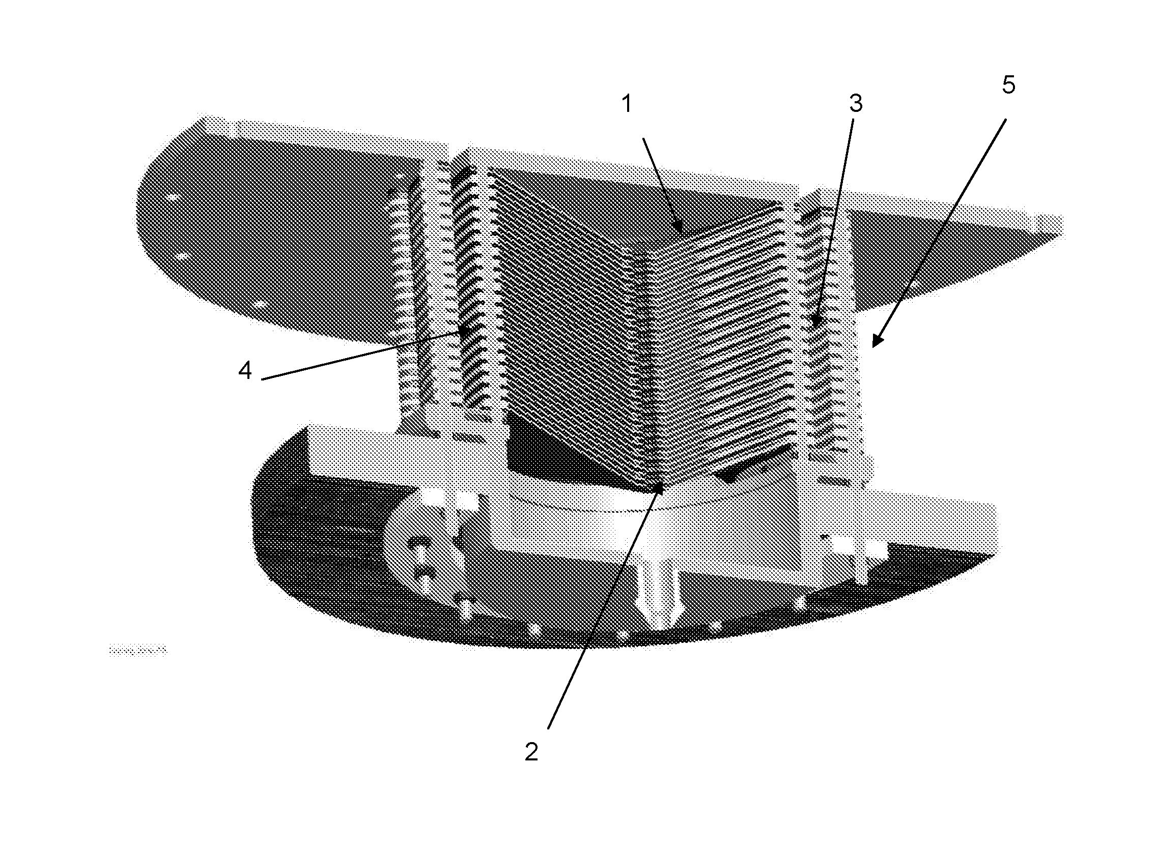
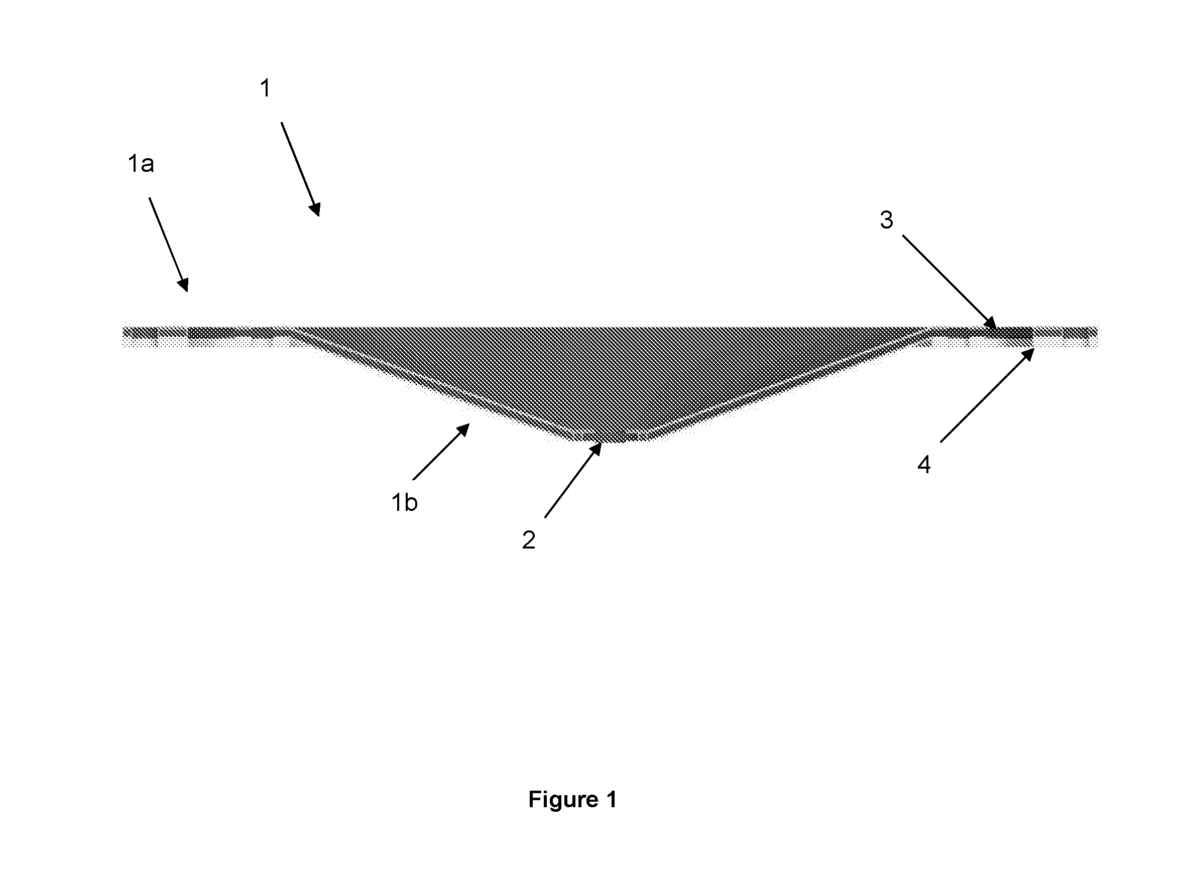
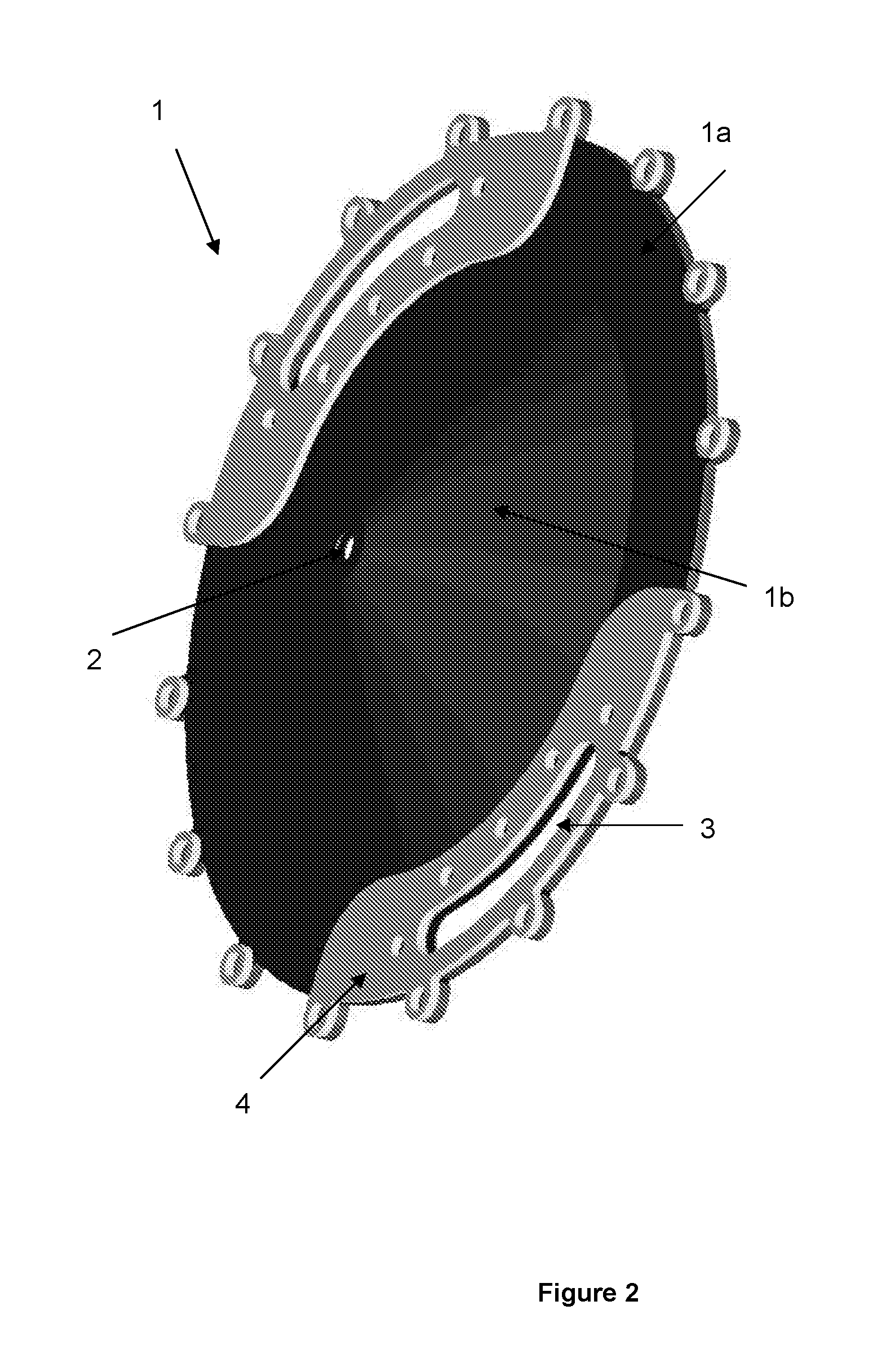
[0034]The embodiment of the combined vacuum evaporator and condenser is illustrated in FIG. 4, whereas details about the condenser are shown in FIG. 3. The condenser and evaporator plates are shown in FIGS. 1-2.

[0035]Specifically the fresh water generator comprises an evaporator unit (6) for evaporation of water to be treated, such as sea water, and a condenser unit (5) for condensing evaporated water from the evaporator unit ...


PUM

PropertyMeasurementUnit
Fractionaaaaaaaaaa
Areaaaaaaaaaaa

Abstract

There is provided a combined evaporator and condenser for a fresh water generator. The generator comprises an evaporation unit into which is introduced water to be treated (typically seawater) heated to at least a saturation temperature for the pressure in the evaporation unit for generating vapor by evaporating water from the seawater, and the condenser unit for condensing the evaporated fresh water. Moreover the generator comprises circulation means for returning the brine, after being evaporated in the evaporation part. The generator utilizes specially designed stacked evaporator and condenser plates having a circular form with a flat peripheral portion and a cone like central portion with an aperture in the centre of the plates providing.

Description

FIELD OF THE INVENTION[0001]The present invention relates to a single stage vacuum evaporator, in particular for fresh water generators with a boiler and at least one heat exchanger.BACKGROUND OF THE INVENTION[0002]Fresh water generating apparatuses presently in practical use as seawater desalination apparatuses are largely divided into those using evaporation methods and membrane methods (reverse osmosis, etc.). The membrane method is superior to the evaporation method from an economical point of view; however, the membrane method requires high-level pretreatment techniques depending on the properties of the seawater, and may cause degradation of the membrane without appropriate pretreatment. The evaporation method is highly valued in terms of reliability and usability.[0003]Among the several types of the fresh water generating apparatuses using the evaporation method, those most typically used are a multi-stage flash-evaporation fresh water generating apparatus (hereinafter referr...

Claims


Application Information

Patent Timeline
IPC IPC(8): C02F1/08B01D1/30C02F1/04B01D1/22
CPCC02F1/08B01D1/221C02F2103/08C02F1/042B01D1/30B01D1/223B01D3/06B01D5/006C02F1/06F28D9/0012F28D9/0043Y02A20/124
Inventor WILLUM, MADS
Owner HYDROFOSS APS
Why Eureka
Eureka Blog
Learn More