Earth Pressure Balance Shield Machine without Cutter Disk

Active Publication Date: 2015-02-12
CHINA RAILWAY ENGINEERING EQUIPMENT GROUP CO LTD
View PDF0 Cites 3 Cited by
  • Summary
  • Abstract
  • Description
  • Claims
  • Application Information

AI Technical Summary

Benefits of technology

[0019]In the shield machine of the present invention, the blades of spiral waste collecting member at different shaft member are arranged at an opposite direction such that the rotation direction of different shaft members are in

Problems solved by technology

Since the speed of action of the cutterhead is very low (a few rotation per minute), the linear v

Method used


Image

  • Earth Pressure Balance Shield Machine without Cutter Disk
  • Earth Pressure Balance Shield Machine without Cutter Disk
  • Earth Pressure Balance Shield Machine without Cutter Disk

Examples


embodiment 1

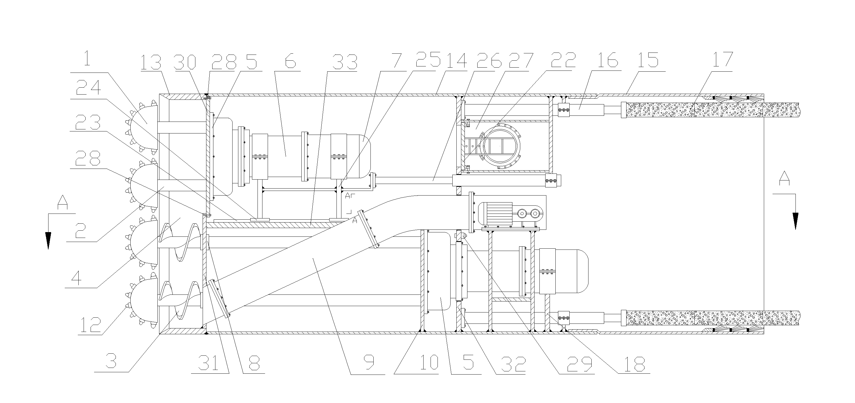
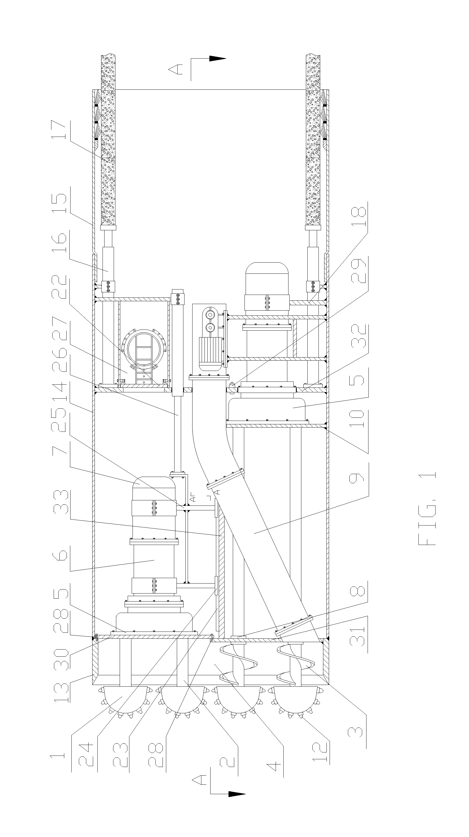
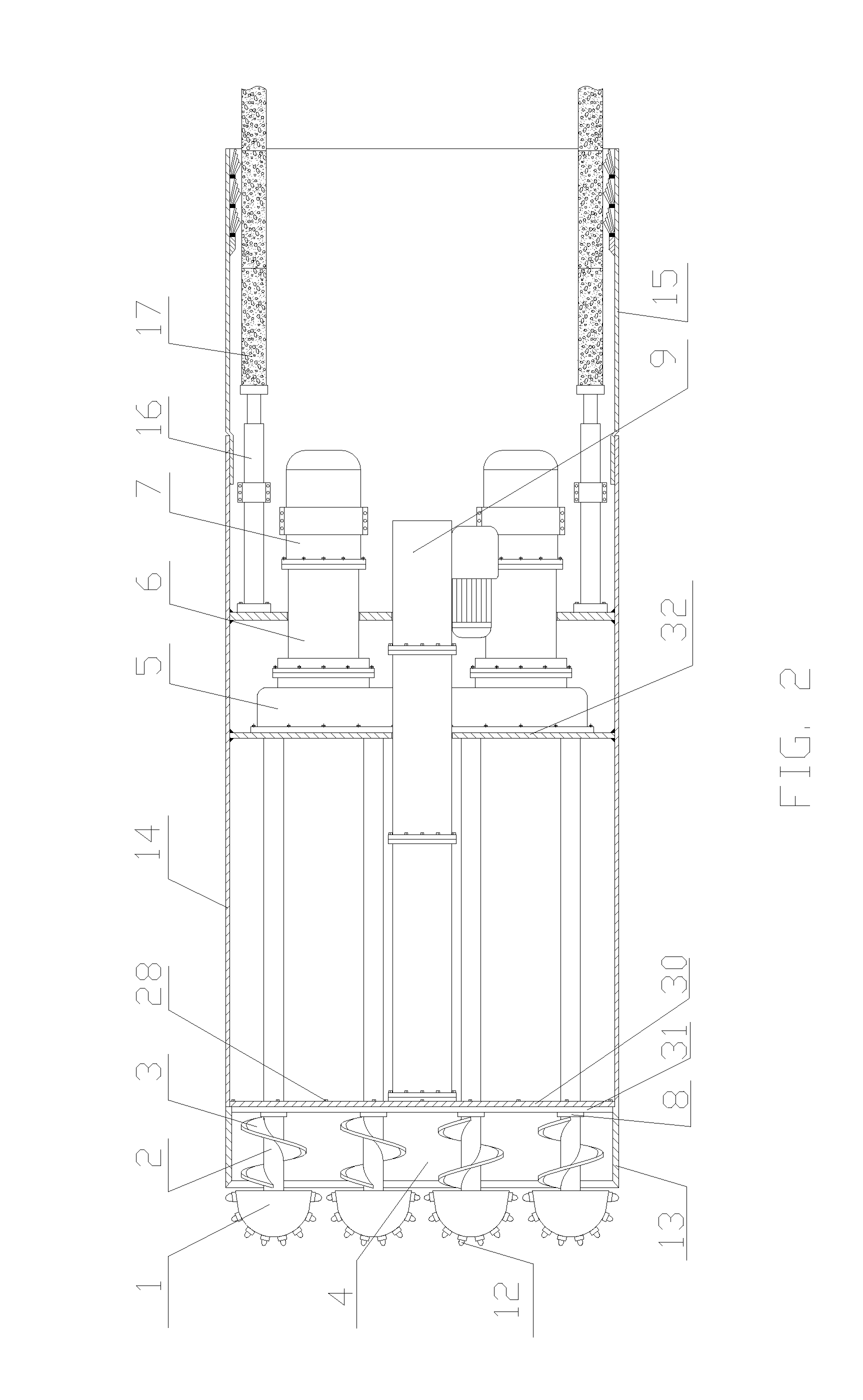
[0026]According to this preferred embodiment of the present invention, the earth pressure balance shield machine has a rectangular construction and no disc cutter arrangement is employed. The earth pressure balance shield machine according to this preferred embodiment of the present invention is arranged for tunnel excavation in which the tunnel has a rectangular cross-section, which is shown in FIG. 1 to FIG. 3 of the drawings.

[0027]According to the earth pressure balance shield machine of this preferred embodiment of the present invention, an electric motor is employed as a driving motor 7 and a flexible conveyor with scraper arrangement is employed as a waste conveyor 9.

[0028]According to this preferred embodiment of the present invention, the earth pressure balance shield machine comprises a cutting unit 1, a shaft member 2, a spiral waste collecting member 3, an earth pressure balance cabin 4, a transfer case 5, a reducer 6, a driving motor 7, a waste conveyor 9, a partition un...

embodiment 2

[0033]According to this preferred embodiment of the present invention, the earth pressure balance shield machine has a cylindrical construction and no disc cutter arrangement is employed. The earth pressure balance shield machine according to this preferred embodiment of the present invention is arranged for tunnel excavation in which the tunnel has a circular cross-section. FIG. 4 refers to a left end view of the earth pressure balance shield machine of this embodiment.

[0034]According to the earth pressure balance shield machine of this preferred embodiment of the present invention, a hydraulic motor is employed as a driving motor 7 and a relay-style flexible screw conveyor is employed as a waste conveyor 9. All other structural construction and connection relationship between different parts are the same as that of embodiment 1.

[0035]In the embodiment 1, a hydraulic motor can also be used for the driving motor 7 and a relay-style flexible screw conveyor can also be used as a waste...


PUM


Abstract

An EPB shield machine without disc cutter, which includes a partition unit formed by a moveable partition member (30) and a stationary partition member (31), a front shield unit (13) including a cutting unit (1) with cutting head (11) and cutting teeth (12), a shaft member (2) connected to the cutting head (11) and a power transmission unit formed by a transfer case (5), a reducer (6) and a driving motor (7). In the power transmission unit at an upper portion of the machine, the transfer case (5) is fixedly to the moveable partition member (30), a sliding arrangement supports the reducer (6) and the driving motor (7), which are connected to the transfer case (5, and a telescopic cylinder (26) is connected to the sliding arrangement. The machine has advantages of high cutting efficiency, balanced service life, high directional construability and high adaptability to tunnel cross section.

Description

BACKGROUND OF THE PRESENT INVENTION[0001]1. Field of Invention[0002]The present invention relates to the technical field of shield machine, and more particularly to an earth pressure balance shield machine without disc cutter arrangement.[0003]2. Description of Related Arts[0004]At present, existing earth pressure balance shield machines in in this country or aboard all utilize a disc cutter arrangement in their cutting system. In cylindrical shield machines, the disc cutter performs a circular movement; while in shield machines of rectangular, oval or other special shape, the disc cutter performs a planar movement through a crank linking arrangement, a swing arrangement or a profiling arrangement. Based on the geological condition and the engineering requirements, different types of cutting members such as hob, cutter or scraper are installed on the cutterhead. The cutting members move along with the cutterhead and no active rotation of the cutting members is allowed. Since the spe...

Claims


Application Information

Patent Timeline
IPC IPC(8): E21D9/08
CPCE21D9/081E21D9/08E21D9/03
Inventor LI, JIANBINHE, YULIAN
Owner CHINA RAILWAY ENGINEERING EQUIPMENT GROUP CO LTD
Why Eureka
Try Eureka