High accuracy pulse duty-cycle calculation implementation for power converter's PWM control apparatus

US20150042294A1Inactive Publication Date: 2015-02-12WEI QI CUI +2

Image

  • High accuracy pulse duty-cycle calculation implementation for power converter's PWM control apparatus
  • High accuracy pulse duty-cycle calculation implementation for power converter's PWM control apparatus
  • High accuracy pulse duty-cycle calculation implementation for power converter's PWM control apparatus

Examples


Embodiment Construction

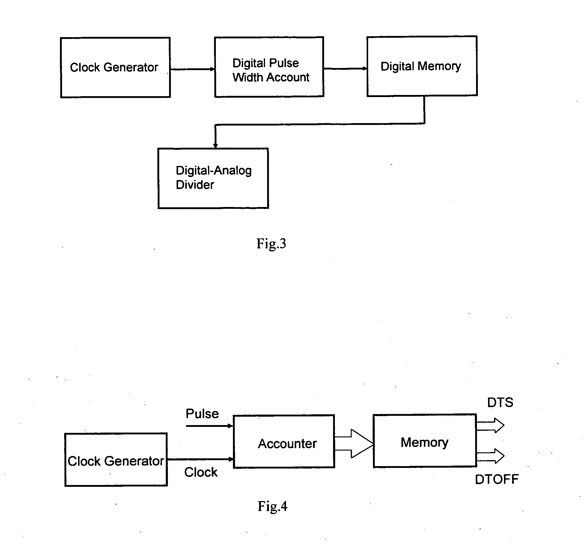
[0014]FIGS. 4 and 5 show detailed embodiment of the “high accuracy pulse duty-cycle calculation hardware implement scheme” function block diagram for clock generator block, digital pulse width account block, digital memory block and digital-analog divider block with two digital-analog converters.

[0015]The clock generator block, digital pulse width account block, digital memory block can be implemented with regular digital circuit, that is, with digital clock, digital accouter and register.

[0016]The digital-analog divider block is composed of operation amplifier A, MOSFET Q, weight resistor network RA, current mirror ICOUPLE, weight resistor network RB. The operation amplifier A, MOSFET Q and weight resistor network RA consist of a current source. The output current of the current source is determined with a reference voltage VREF over the weight resistor network RA. The current source is coupled through the current mirror ICOUPLE into the weight resistor network RB and generates the...


PUM


Abstract

The high accuracy pulse duty-cycle calculation hardware implementation scheme is composed of a clock generator block, digital pulse width account block, digital memory block to store pulse width in digital and digital-analog divider block with two digital-analog converters. The digital pulse width account block is used to account the two pulse width of a pulse, e.g. turn-on time TON, turn-off time TOFF, cycle time TS or other time variable in digital method. The digital memory block is used to store digital information from the digital pulse width account block until next cycle. The digital-analog divider block outputs the ratio of two pulse widths in analog signal based on two stored digital pulse widths from the digital memory block

Description

BACKGROUND OF THE INVENTION[0001]The present invention relates to the pulse duty-cycle calculation implement scheme. More specifically, the invention relates to high accuracy pulse duty-cycle calculation hardware implementation scheme for several power converter's PWM control apparatus.[0002]In the existing pulse duty-cycle calculation implementation scheme as shown in FIG. 1, there are two steps. The first is to convert a pulse width into a related analog signal and sample-hold the analog signal; The second is to use an analog divider to obtain the ratio of two pulse widths. More particularly, in the first step, the pulse width signal is converted into an analog signal through an integrator circuit, after then the analog signal is sample-holded. In the second step, two sample-holded analog signals are inputted into two inputs of divider to get the ratio of two pulse widths.[0003]Due to a wide and dynamic range of pulse widths, it is hard to implement the integrator and sample-hold ...

Claims


Application Information

Patent Timeline
12 Feb 2015
Publication
US20150042294A1
IPC
H02M3/04
CPC
H02M3/04; H02M3/157; H03K7/08
Inventors
WEI, QI CUI; WENG, DA FENG