Methods and apparatus for determining focus

Active Publication Date: 2015-02-12
KLA TENCOR CORP
View PDF4 Cites 67 Cited by
  • Summary
  • Abstract
  • Description
  • Claims
  • Application Information

AI Technical Summary

Benefits of technology

[0009]The following presents a simplified summary of the disclosure in order to provide a basic understanding of certain embodiments of the invention. This summary is not an extensive overview of the disclosure and it does not identif

Problems solved by technology

These plots are generally harder to obtain since measuring these shapes is often a difficult endeavor.
As should be appreciated, using a portion of the device structure may be more difficult, but it tends to be more accurate since it is a portion of the device structure.
Also, fewer measurements are made on a product wafer than on a focus exposure matrix wafer due to time constraints in production.
Using focus solutions determined from many focus exposure matrix measurements can average out measurement errors, stepper errors, and the like.
Although an optimal or best focus can be determined, a lithography tool may actually program a differe

Method used


Image

  • Methods and apparatus for determining focus
  • Methods and apparatus for determining focus
  • Methods and apparatus for determining focus

Examples


Embodiment Construction

[0027]In the following description, numerous specific details are set forth in order to provide a thorough understanding of the present invention. The present invention may be practiced without some or all of these specific details. In other instances, well known process operations have not been described in detail to not unnecessarily obscure the present invention. While the invention will be described in conjunction with the specific embodiments, it will be understood that it is not intended to limit the invention to the embodiments.

INTRODUCTION

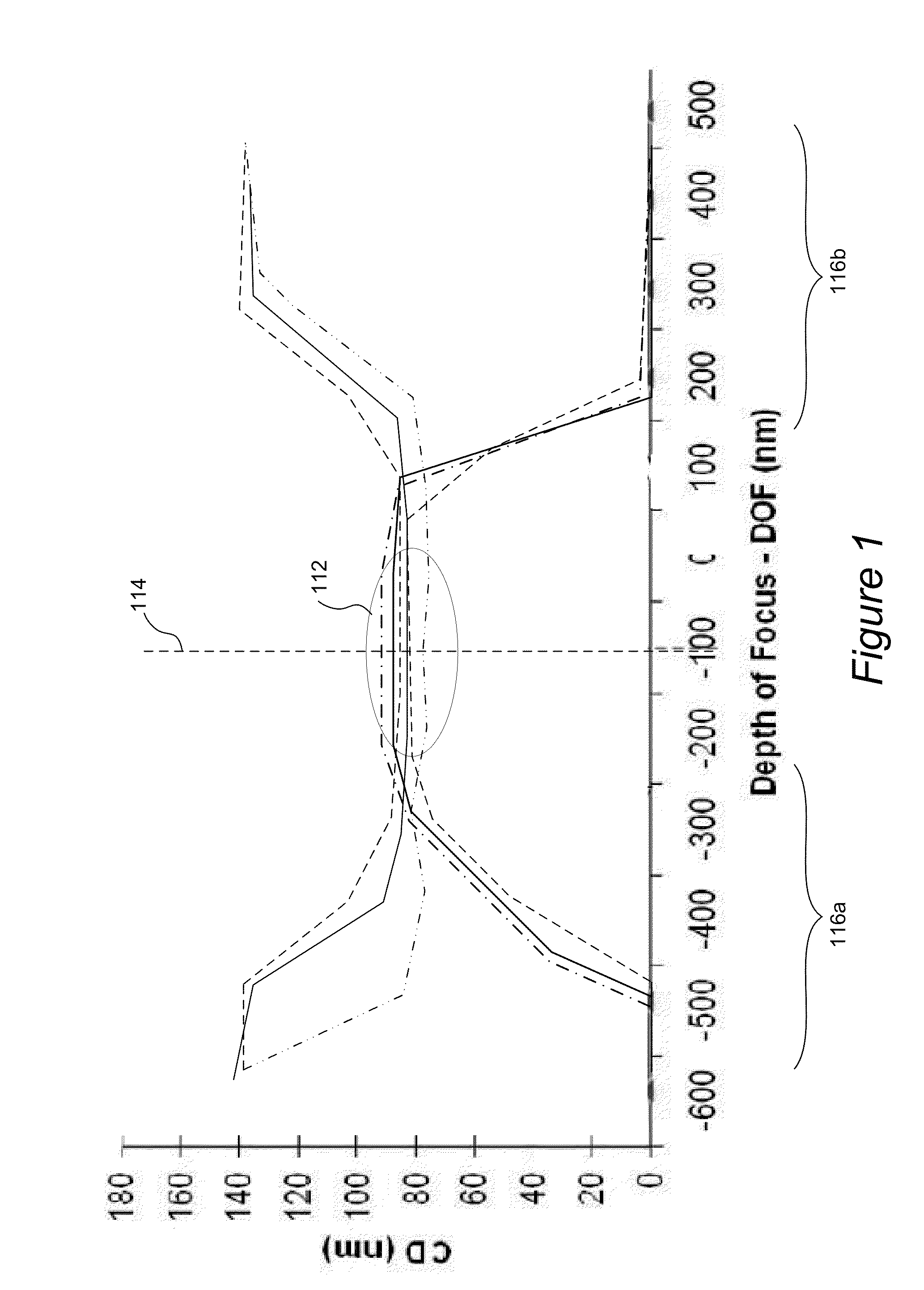
[0028]A focus-exposure matrix obtained from a FEM wafer, by way of example, may be visualized using a Bossung Plot to facilitate determination of a lithography process window. The Bossung Plot generally plots CD vs. focus position for varying levels of exposure, such as the example in FIG. 1. As shown, varying levels of exposure are plotted as contour lines with CD representing the Y axis and focus position representing the X axis of the gr...


PUM


Abstract

Disclosed are apparatus and methods for determining optimal focus for a photolithography system. A plurality of optical signals are acquired from a particular target located in a plurality of fields on a semiconductor wafer, and the fields were formed using different process parameters, including different focus values. A feature is extracted from the optical signals related to changes in focus. A symmetric curve is fitted to the extracted feature of the optical signals as a function of focus. An extreme point in the symmetric curve is determined and reported as an optimal focus for use in the photolithography system.

Description

CROSS-REFERENCE TO RELATED APPLICATIONS[0001]This application claims the benefit of prior application U.S. Provisional Application No. 61 / 864,527, filed 10 Aug. 2013 by Stilian Ivanov Pandev, which application is herein incorporated by reference in its entirety for all purposes.TECHNICAL FIELD OF THE INVENTION[0002]The present invention relates generally to methods and systems for determination of photolithography parameters and, more specifically, to determination of focus parameters using focus exposure matrix (FEM) wafers.BACKGROUND[0003]Photolithography or optical lithography systems used in the manufacture of integrated circuits have been around for some time. Such systems have proven extremely effective in the precise manufacturing and formation of very small details in the product. In most photolithography systems, a circuit image is written on a substrate by transferring a pattern via a light or radiation beam (e.g., UV or ultraviolet light). For example, the lithography sys...

Claims


Application Information

Patent Timeline
IPC IPC(8): G03F9/00G03F7/20
CPCG03F7/70641G03F9/7026
Inventor PANDEV, STILIAN IVANOV
Owner KLA TENCOR CORP
Why Eureka
Try Eureka